|
|
|
Categories
|
|
Information
|
|
Featured Product
|
|
|
 |
|
|
There are currently no product reviews.
 ;
Excellent manual including schematics. The service was great and the manual helped complete the job.
;
It was magic after so many years to still be able to source this info. It was equally amazing to return my Pioneer receiver to it near new sound quality AFTER NEARLY 30 YEARS! Thank you for this ability!
;
Very quick and easy website to use and fast download of manual, quality of manual is excellent and will be pleased to use this service again in the future, thanks so much!
 ;
Easy and secure way to get a complete service manual of a vintage hifi component. Only some parts of the print copy are dificult to read. Nice price!
;
The manual is an excellent reproduction with complete schematics, made troubleshooting and repair a simple process.
1
2
3
4
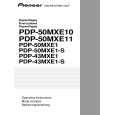
3 X CONNECTOR A, B Assy, 43 SCAN A, B Assy
A
X CONNECTOR A and B Assy
1
6
Remove the enclosure sheet 1.
6
6
43 X DRIVE Assy
Note: Enclosure sheet 1 is attached to comply with the safety standards. Make sure that it will not be shifted or peeled off. If it is peeled off, securely reattach it in its original place.
2 3 4
B
Remove the jumper wire by removing the flat clamp. Remove the one nyron rivet. Remove the one screw.
6 2
Flat clamp
Front chassis VR (43M)
6 4
1
3 5
Note: Be sure to remove this screw. If you don't, the connector on the LED OPT Assy may be damaged.
Enclosure sheet 1
LED OPT Assy
5 6
Remove the LED OPT Assy. Remove the front chassis VR (43M) by removing the five screws.
7 8 9
C
Remove the seven screws. Remove the two spacers. Remove the X CONNECTOR A and B Assy.
43 X DRIVE Assy
7 8
�3
7
�4
8 9
X CONNECTOR B Assy
Note when reassembling the front chassis VR (43M) Remove or loosen the screws that secure the panel holder in order not to damage the front protect panel Assy.
9
X CONNECTOR A Assy
43 SCAN A and B Assy
D
1 2 3 4
Remove the one nylon rivet. Remove the jumper wire by removing the flat clamp. Remove the one screw. Remove the front chassis VL (43M) by removing the five screws.
4
4
43 Y DRIVE Assy
4
4
Front chassis VL (43M)
Flat clamp
4 2
3
1
E
5 6 7 8
Remove the four screws. Disconnect the two pin connectors. Remove the six spacers.
43 Y DRIVE Assy
65 7 7 8
55 7 7
56 7 8 7
Remove the 43 SCAN A and B Assy.
Note when reassembling the front chassis VL (43M) Remove or loosen the screws that secure the panel holder in order not to damage the front protect panel Assy.
F
43 SCAN B Assy
43 SCAN A Assy
144
1 2
PDP-504CMX/1
3 4
|
|
|
> |
|