|
|
|
Categories
|
|
Information
|
|
Featured Product
|
|
|
 |
|
|
There are currently no product reviews.
 ;
manual excelente completo , diagramas y esquemas bien presentados y buena calidad de imagen.
;
muy buen manual completo de buena calidad de impresion preciso y detallado , muy útil para la reparación.
;
The service manual is a good quality scan of the Panasonic NV-850, which is electrically identical to the Philips VR 6920, but mecanically just nearly.
;
The service manual is a good quality scan of the Blaupunkt RTV-404, which is electrically and mecanically identical to the Panasonic NV-830.
;
completo manual bien detallado y de buena calidad de impresion , se echa en falta los esquemas de placa y parte de algun diagrama.
5
6
7
8
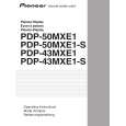
Charged Section
The places where the commercial AC power is used without passing through the power supply transformer. If the places are touched, there is a risk of electric shock. In addition, the measuring equipment can be damaged if it is connected to the GND of the charged section and the GND of the non-charged section while connecting the set directly to the commercial AC power supply. Therefore, be sure to connect the set via an insulated transformer and supply the current.
High Voltage Generating Point
The places where voltage is 100 V or more besides the live parts are described above. You must not touch them, since there is risk of electric shock. The VSUS voltage remains for several minutes after the power to the unit is turned off. These places must not be touched until about 10 minutes after the power is turned off, or it is confirmed with a tester that there is no residual VSUS voltage. 1. POWER SUPPLY Unit.....................................................(223V) 2. 50 X DRIVE Assy ...........................................(�230V to 223V) 3. 50 Y DRIVE Assy ...........................................................(353V) 4. 50 SCAN A Assy ............................................................ (353V) 5. 50 SCAN B Assy ............................................................ (353V) 6. X CONNECTOR A Assy ................................(�230V to 223V) 7. X CONNECTOR B Assy ............................... (�230V to 223V) Discharge the VSUS voltage, as shown below: [Method for discharging the VSUS voltage] 1. Set DRF_SW on the DIGITAL VIDEO Assy to ON (Drive OFF status). �1, �2 2. Leave the switch at that position for about 20-30 seconds. 3. If the power is on, turn it off. Then return DRF_SW to the OFF position. �3 Notes �1: You can also set the unit to "Drive OFF status" by sending the "DRF" RS232C command from the PC. �2: DRF_SW can be switched whether the power is on or off. �3: Power-down will occur if DRF_SW is set to OFF while the power is on. (See "7.1.5 POWER ON/OFF FUNCTION FOR THE LARGE-SIGNAL SYSTEM".)
POWER SUPPLY Unit 50 X DRIVE Assy X CONNECTOR B Assy
A
1. Power Cord 2. AC Inlet with Filter 3. Power Switch (S1) 4. Fuse (In the POWER SUPPLY Unit) 5. STB Transformer and Converter Transformer (In the POWER SUPPLY Unit) 6. Other primary side of the POWER SUPPLY Unit
B
C
50 inch model
: Part is Charged Section. : Part is the High Voltage Generating Points other than the Charged Section. 50 SCAN B Assy 50 Y DRIVE Assy
D
E
50 SCAN A Assy
Power Switch (S1)
AC Inlet with Filter
X CONNECTOR A Assy Power Cord
F
Fig.1 Charged Section and High Voltage Generating Point (Rear view)
PDP-504CMX/1
5 6 7 8
5
|
|
|
> |
|