|
|
|
Categories
|
|
Information
|
|
Featured Product
|
|
|
 |
|
|
There are currently no product reviews.
 ;
The item received was as described, as expected. I was pleased with the order. Thank you.
 ;
Superb rendition. Drawings (schematics) complete and unabridged. I do a great deal of vintage audio restoration. Documentation is essential for successful repairs. I have found sources over the years that offer good documentation, but rarely all that is necessary. Owner's Manuals has filled that void with complete and legible documentation. They have narrowed my "favorites" to a more manageable collection. This Denon manual in particular contained the latest revisions level, and offered alterations favorable to updating the item. The Illustrated Parts Breakdown (IPB) was well enough detailed to simplify part symbols and physical locations. You will not be disappointed!
;
Clear and concise. Saved me a lot of time and money.
;
Superb manual. Exactly what I ordered and made available in a very timely manner.
;
very fast detailed and accurate hope to do business again
1
2
3
4
DELAY ADJUSTMENT OF THE CONTROL SIGNAL (SUS-B)
A
1 Measure the delay time for the SUS-U signal. 2 Check the delay time for the SUS-B signal. Adjust the variable control so that the SUS-B delay time becomes "SUS-U delay time + α ± 5 nsec." Note: For details on measuring points of waveform, see the figure below.
1.5 V SUS-U signal (input to the DRIVE Assy) 5V SUS-U signal (input to the DK module)
B
SUS-U delay time � Tsus-u 1.5 V SUS-B signal (input to the DRIVE Assy) 5V SUS-B signal (input to the MSK module) SUS-B delay time � Tsus-b
C
Value of α
SUS-B delay time: � Tsus-b Adjust so that "� Tsus-b = � Tsus-u + α ± 5 nsec," using the variable controls shown in the table below:
Assy X DRIVE Y DRIVE
VR VR1002 VR2010
Time 70 nsec 85 nsec
DELAY ADJUSTMENT OF THE CONTROL SIGNAL (SUS-G)
1 Measure the delay time for the SUS-D signal. 2 Check the delay time for the SUS-G signal. Adjust the variable control so that the SUS-G delay time becomes "SUS-D delay time + β ± 5 nsec." Note: For details on measuring points of waveform, see the figure below.
1.5 V SUS-D signal (input to the DRIVE Assy) 5V SUS-D signal (input to the DK module) SUS-D delay time � Tsus-d SUS-G signal (input to the DRIVE Assy)
E
D
1.5 V
5V SUS-G signal (input to the MSK module) SUS-G delay time � Tsus-g Value of β
SUS-G delay time: � Tsus-g
F
Assy X DRIVE Y DRIVE
VR VR1001 VR2011
Time 120 nsec 100 nsec
Adjust so that "� Tsus-g = � Tsus-d + β ± 5 nsec," using the variable controls shown in the table below:
132
1 2
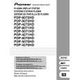
PDP-6071PU
3 4
|
|
|
> |
|