|
|
|
Categories
|
|
Information
|
|
Featured Product
|
|
|
 |
|
|
There are currently no product reviews.
 ;
As Always you can find here manuals even of difficult TV scheme which are scan in almost perfect way.clear and fast!!!!!
Great work thanks!
;
Incredibly clear!!!! Well done, complete and wonderful. It could not better than this!!!!
 ;
Thank You for fast delivery for the sheme.
Everything allright.
Thanks & best regards Franz
;
again you did a very good job. It was fast too. Photocopy are really readable and clear
;
Probably it never existed a 1081 official service manual from Commodore, it's look more like a NAPCEC service manual & diagrams compilation of the 1084 series and his variants, like the nap6523, 8cm505, 1084S, 1084P and obviously the 1081. It's more complete than other scans and the quality of the scans also are far superior. It has two circuit diagrams variants of the 1081, mono and stereo versions. It doesn't include a diagram for the Philips CM8500 or CM8501, they look like the 1081 but they are slightly different.
1
2
3
4
A
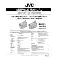
[5] MAIN ASSY
Flowchart of Failure Analysis for The MAIN Assy
Failure analysis for the MAIN Assy => MA1
The STB LED does not light although STB 3.4 V power is supplied.
Does the POWER switch on?
B
No
Turn the POWER switch on.
Yes Is resetting of the IF microcomputer canceled? Yes Is the voltage at Pin 3 of the M11 connector High? Yes Is the M11 connector securely connected? Yes Is the cable that is connected to the M11 connector broken? No No problem with the MAIN Assy. Check the LED Assy. Yes No Securely connect the M11 connector. No Replace the MAIN Assy.
Failure in the line between the IF microcomputer and M11 connector.
No
Replace the MAIN Assy.
Failure in the RST IC (IC8302) output or its peripheral circuits.
C
Replace the cable (J116).
Failure analysis for the MAIN Assy => MA2
The RELAY port does not work. The power is not turned on.
D
Is the voltage at Pin 50 of the M4 connector 3.4 V? Yes
No
Replace the MAIN Assy.
Relay control is unable unless it supplies a power supply to the module microcompute.
Are the voltages (1.5 V/2.5 V/3.4 V) No supplied to the main microcomputer? Yes Is voltage at REQ_IF on the MAIN Assy High (3.3 V)? Yes
E
Replace the MAIN Assy.
No
Can the unit be turned on, using the remote control unit? Yes
No
Replace the cable (J117) that connects between the IR and MAIN Assys.
NG Replace the IR Assy. NG Replace the MAIN Assy.
Can the unit be turned on, using the Power switch on the unit? Yes
No
Replace the cable (J116) that connects between the SIDE KEY and MAIN Assys.
NG Replace the SIDE KEY Assy. NG Replace the MAIN Assy.
Can the unit be turned on, using RS-232C commands? Replace the MAIN Assy.
F
No
Replace the 50P cable (J213) that NG Replace the IO_AUDIO Assy. connects between the IO_AUDIO and MAIN Assys. NG Replace the MAIN Assy.
52
1 2
PDP-LX509A
3 4
|
|
|
> |
|