|
|
|
Categories
|
|
Information
|
|
Featured Product
|
|
|
 |
|
|
There are currently no product reviews.
 ;
It paid to find this Service Manual, couldn't find it anywhere else. Exactly what I wanted. Received within 24 hours.
;
Complete manual with clear schematic diagrams and printed circuit board layouts of two variants of the headset and the transmitter an old and a new version.
Also shows how the headset and the transmitter is opened and how transmitter and receivers can be adjusted and where to measure.
I had no problems to repair the headset using this service manual.
 ;
Excellent printing quality. A complete and very useful manual with all details.
;
This is a great site. I placed my order and by the next am it was available for download. Had some problems with some missing copy on some pages. Once I brought the error to the OMC's attention, the issue was resolved. I'll come back again.
;
Mi spiace per non poter scrivere in inglese... ma sono veramente soddisfatto del servizio offerto. Grazie..!!
5
6
7
8
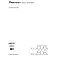
5.2.2 POWER SUPPLY UNIT
Flowchart of Failure Analysis for The POWER SUPPLY Unit
A
Failure analysis for the POWER SUPPLY Unit => PS1
STB 3.3 V power is not output.
Is the cable connected firmly to the P4 connector? Yes Is the cable to the P4 connector broken? No Is the cable connected firmly to the P9 connector? Yes Is the cable to the P9 connector broken? No Is the fuse (F001) blown? No Is one of the limiting resistors (R001/FR001) blown? No
No
Properly connect the cable between the P4 and D23 connectors.
Yes
Replace the defective cable (J104). POWER SUPPLY Unit.
Check the voltage at the DIGITAL Assy and
No
Properly connect the cable between the P9 and M2 connectors.
B
Yes Replace the defective cable (J106).
Yes Replace the POWER SUPPLY Unit.
Yes Replace the POWER SUPPLY Unit.
Check the resistance between F001 lead and the D002 anode, using a tester.
C
The POWER SUPPLY Unit is normal.
Failure analysis for the POWER SUPPLY Unit => PS2
The power is not on, even though the RELAY port is active.
No Is the relay (RL002) on? Yes No Is the PFC voltage normal? Yes The POWER SUPPLY Unit is normal.
Replace the POWER SUPPLY Unit.
� Check the relay operation at the terminal (Pin 11 of P4). (Voltage: 3.3 V) � Check the relay sound (click).
Replace the POWER SUPPLY Unit.
� Check the voltage between F301 lead (PFC OUT) and heat sink (primary GND) nearest F301. � The voltage must be around 390 V. Caution: High voltage!
D
Failure analysis for the POWER SUPPLY Unit => PS3
The cells of the panel do not light normally.
Is the VADR voltage within the specified values? Yes Is there a fluctuation in the VADR voltage? No Is the VSUS voltage within the specified range? Yes Is there a fluctuation in the VSUS voltage? No The POWER SUPPLY Unit is normal.
No
Replace the POWER SUPPLY Unit.
The specified voltage values are between 57 and 63 V.
E
Yes
Replace the POWER SUPPLY Unit.
The ripple must be within 5 V.
No
Replace the POWER SUPPLY Unit.
The specified voltage values are between 205 and 215 V (VSU: 125/35°C).
Yes Replace the POWER SUPPLY Unit.
The ripple must be within 10 V.
F
PDP-LX6080D
5 6 7 8
47
|
|
|
> |
|