|
|
|
Categories
|
|
Information
|
|
Featured Product
|
|
|
 |
|
|
There are currently no product reviews.
 ;
The item received was as described, as expected. I was pleased with the order. Thank you.
 ;
Superb rendition. Drawings (schematics) complete and unabridged. I do a great deal of vintage audio restoration. Documentation is essential for successful repairs. I have found sources over the years that offer good documentation, but rarely all that is necessary. Owner's Manuals has filled that void with complete and legible documentation. They have narrowed my "favorites" to a more manageable collection. This Denon manual in particular contained the latest revisions level, and offered alterations favorable to updating the item. The Illustrated Parts Breakdown (IPB) was well enough detailed to simplify part symbols and physical locations. You will not be disappointed!
;
Clear and concise. Saved me a lot of time and money.
;
Superb manual. Exactly what I ordered and made available in a very timely manner.
;
very fast detailed and accurate hope to do business again
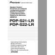
ORDER NO.
RRV3010
PDP-S21-LR
PDP-S21-LR
PDP-S21-LR
XIN/CN
SPEAKER SYSTEM
XIN/E
65S This service manual is intended for qualified service technicians; it is not meant for the casual do-it-yourselfer. Qualified technicians have the necessary test equipment and tools, and have been trained to properly and safely repair complex products such as those covered by this manual. Improperly performed repairs can adversely affect the safety and reliability of the product and may void the warranty. If you are not qualified to perform the repair of this product properly and safely, you should not risk trying to do so and refer the repair to a qualified service technician. WARNING This product contains lead in solder and certain electrical parts contain chemicals which are known to the state of California to cause cancer, birth defects or other reproductive harm. Health & Safety Code Section 25249.6 � Proposition 65
FOR PRECAUTION OF REASSEMBLY AND DISASSEMBLY
The woofer is attached to the baffle by 4 internal screws. To detach it, first unfasten screws that attached to the baffle from the back side of the cabinet. Then unfasten those screws. When attaching it, face its terminal downward. When exchange the woofer, attach the packing (SEB1256) to its terminal. Refer to � PRODUCT APPEARANCE �. The tweeter is attached to the baffle by 2 internal screws.To detach it, first unfasten screws that attached to the baffle from the back side of the cabinet. Then unfasten those screws. When attaching it, face its large terminal upward. The choke coil of the Network Assy is attached to the cabinet by an internal screw with adhesive. To detach it, unfasten its screw.
4-1, Meguro 1-chome, Meguro-ku, Tokyo 153-8654, Japan PIONEER ELECTRONICS (USA) INC. P.O. Box 1760, Long Beach, CA 90801-1760, U.S.A. PIONEER EUROPE NV Haven 1087, Keetberglaan 1, 9120 Melsele, Belgium PIONEER ELECTRONICS ASIACENTRE PTE. LTD. 253 Alexandra Road, #04-01, Singapore 159936
PIONEER CORPORATION
PIONEER CORPORATION 2004
T-ZZE OCT. 2004 Printed in Japan
|
|
|
> |
|