|
|
|
Categories
|
|
Information
|
|
Featured Product
|
|
|
 |
|
|
There are currently no product reviews.
 ;
Excellent printing quality. A complete and very useful manual with all details.
;
Even if the PDF is a scan, I can read the information I need.
The price is affordable and the service (mail sending) is very fast.
Thanks ! Regards. William (Fan of Kenwood)
;
Very good quality original datasheet!I like this amazing website!!!!!!
 ;
Excellent just what I needed to replace the electrolytic caps and make this old gem a beauty again. Was as scan of the original photocopied service manual.
;
It was helpful to get schematic with waveforms in important points and lot of service information. Manual is good quality, fast delivered. Of course it is hardcopy of paper one with all its disadvantages.
PDR-L77
6.5.2 M-S Mix Ratio Adjustment
Test Point Adjustment Point Adjustment Value Symptom when out of adjustment [Procedure]
(1) Press the AUTO/MANUAL button so that "02 F3" appears on the FL display. (2) Press the FINALIZE button for focus-in. (3) Press the PLAY button for CAV-servo spindle kick (the status where the spindle rotates with the focus servo on and tracking servo off). (4) Adjust with the RECORD button and the REC MUTE button until the value to be reached is obtained. (5) Press the SET button to register the adjustment. Once the adjustment is registered with the SET knob, "D.VOL" on the FL display lights. (6) Press the STOP button to stop the unit. Note: For adjustment, use the following circuits.
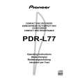
39k� TE 39k� MPP 10 : 1 VC 0.001µF 10:1 probe CH2 0.001µF 10 : 1 CH1 Oscilloscope
CN102 - pin 4 (TE) and pin 3 (MPP) RECORD button and REC MUTE button
Test Disc
STD-903
Adjust until the value of the output signals from pin 4 (TE) and pin 3 (MPP) of CN102 are the same, or the differential output of these signals is minimal. Sound broken, record characteristics deteriorate
Note: Adjustment must be done around mid-radius on a disc.
6.5.3 Tracking Offset Adjustment
Test Point Adjustment Point Adjustment Value
CN102 - pin 4 (TE) RECORD button and REC MUTE button 0 mV ± 10 mV
[Procedure]
(1) Press the AUTO/MANUAL button so that "03 F6" appears on the FL display. (2) Adjust with the RECORD button and the REC MUTE button until the above adjustment value to be reached is obtained. (3) Press the SET button to register the adjustment. Once the adjustment is registered with the SET button, "D.VOL" on the FL display lights.
TE 10 : 1 VC 10:1 probe Oscilloscope
Note: Perform the adjustment in Stop mode. This adjustment is possible with the low-pass filter used in adjustment 5 above attached.
55
|
|
|
> |
|