|
There are currently no product reviews.
 ;
We received the manual in a timely manner and it was exactly what we were expecting. Excellent replacement for original Service Manual.
All schematics are very legible. We are really satisfied.
;
Fast delivery and good quality manual.
Very easily downloadable from a given url.
Will be pleased to buy again from this seller.
;
Ottimo manuale, grafica ferfetta invio rapidissimo. Altissimo livello!!!!!
;
Great PDF easy to read good info needed for replacment of belts and assembly and specs.
;
complete and unabridged very good quality
easy to download.
recieved in two days.
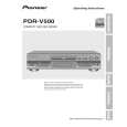
PDR-555RW
6.5.4 Focus Bias Adjustment
Test Point Adjustment Point Adjustment Value
CN354 - pin 1 (RF) DIGITAL SYNCHRO button, RECORD button and REC MUTE button Adjust until RF jitter is minimal or that the eye pattern of the RF waveform is most open.
[Procedure]
(1) Press the DIGITAL SYNCHRO button in Stop mode. Note: Make sure the unit is in Stop mode. (2) Check that "48" appears on the FL display. (3) Press the AUTO/MANUAL button so that "04 34" appears on the FL display. (4) Press the FINALIZE button for focus-in. (5) Press the PLAY button for CAV-servo spindle kick. (6) Press the PAUSE button to close the tracking servo, then set the unit to Playback mode. (7) Adjust with the RECORD and REC MUTE buttons until the above adjustment value to be reached is obtained. Press the SET button to register the adjustment. Once the adjustment is registered with the SET button, "?" on the FL display will disappear. (8) Press the STOP button to stop the unit.
RF 10 : 1 VC 10:1 probe Jitter Meter or Oscilloscope
Note: Adjustment must be done around mid-radius on a disc.
54
|