|
|
|
Categories
|
|
Information
|
|
Featured Product
|
|
|
 |
|
|
There are currently no product reviews.
 ;
Good,readable manual. I found other manuals that were not readable when it came to part ID, but the one downloaded from owner-manual.com was better than expected. I will do buisness with owner-manual.com again.
;
Service Manual that I received was very helpful to me. Thank you.
;
The manual is well organized and is easy to read. The chapters are following normal way to proceed.
;
This scanned manual is well done in that most all the pages except for one is straight and clear- the way I would do them. One page was upside down but that happens. For the money that is charged on this site you get a pretty good deal. Now with complex repairs, I still prefer to us paper manuals which I have to buy at stereomanuals but the one I got here was much less than the $45 he was charging but this is a larger than normal manual for three different units. I am a picky manual user because I have used original manuals from Sony and Teac.
;
Very useful service manual, was exactly what i needed.Good quality,reasonable price.Thank you.
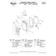
051-9126-00
BS62LV1024STI-70
128 x 8 bit SRAM
051-6709-90
PCM1792DBR
24bit 192kHz DA Converter
Terminal Description pin 1: A 11 pin pin pin pin pin pin pin 2: A 9 3: A 8 4: A 13 5: WE_ 6: CE 2 7: A 15 8: VCC
1 VCC NC 16
: IN : Address signal input. : IN : Address signal input. : IN : Address signal input. : IN : Address signal input. : IN : Write enable signal input. : IN : The chip enable signal input. : IN : Address signal input. : - : Positive voltage supply. : - : Not in use. : IN : Address signal input. : IN : Address signal input. : IN : Address signal input. : IN : Address signal input. : IN : Address signal input. : IN : Address signal input. : IN : Address signal input. : IN : Address signal input. : IN : Address signal input. : IN : Address signal input. :I/O: Data input/output. :I/O: Data input/output. :I/O: Data input/output. : - : Ground. :I/O: Data input/output. :I/O: Data input/output. :I/O: Data input/output. :I/O: Data input/output. :I/O: Data input/output. : IN : The chip enable signal input. : IN : Address signal input. : IN : Output enable signal input.
8 GND 9 7 10 6 11 5 12 4 NC 13 3 14
Terminal Description pin 1: ZERO L pin pin pin pin pin pin pin pin 2: ZERO R 3: M SEL 4: LR CK IN 5: DATA IN 6: B CK IN 7: SCK 8: D GND 9: D VDD
: O : ZERO flag output for Left channel. : O : ZERO flag output for Right channel. : IN : I2C/SPI_ select. : IN : Left/Right clock input. : IN : Serial data input. : IN : Bit clock input. : IN : The system clock pulse input. : - : Digital ground. : - : Positive voltage supply for the digital section. : IN : Chip select for mode control. : IN : Mode control data input. : IN : Mode control clock input. : O : Mode control read back data output. : IN : Reset signal input. : - : Positive voltage supply for the internal analog section. : - : Analog ground. : O : Right channel analog signal current output +. : O : Right channel analog signal current output -. : - : Analog ground. : - : Output current bias. : - : Right channel internal bias. : - : Left channel internal bias. : - : Positive voltage supply for the internal analog section. : - : Analog ground. : O : Left channel analog signal current output +. : O : Left channel analog signal current output . : - : Analog ground. : - : Positive voltage supply for the internal analog section.
2 7 1 VCC 8
pin 9: NU pin 10: A 16 pin 11: A 14 pin 12: A 12 pin 13: A 7 pin 14: A 6 pin 15: A 5 pin 16: A 4 pin 17: A 3 pin 18: A 2 pin 19: A 1 pin 20: A 0 pin 21: D 0 pin 22: D 1 pin 23: D 2 pin 24: GND pin 25: D 3 pin 26: D 4 pin 27: D 5 pin 28: D 6 pin 29: D 7 pin 30: CE 1_ pin 31: A 10 pin 32: OE_ Truth Table
WE_ (pin 5) x x H H L
: IN : Address signal input.
pin 10: MS pin 11: MDI pin 12: MC pin 13: MD pin 14: RSTI pin 15: A VCC pin 16: A GND pin 17: I out R+ pin 18: I out Rpin 19: A GND pin 20: Iref pin 21: V com R pin 22: V com L pin 23: A VCC pin 24: A GND pin 25: I out L+ pin 26: I out Lpin 27: A GND pin 28: A VCC
CE 1_ (pin 30) H x L L L
CE 2 (pin 6) x L H H H
OE_ (pin 32) x x H L x
I/O Operation High Z High Z High Z data out data in
051-7285-08
CD74HC4050PWR
Hex Buffer
051-3042-90
OPA2134UA
4 VEE 5
Dual Operational Amplifier
051-3232-90
uPD29M33T
2 15
3.3V Voltage Regulator
051-3012-90
OP275GS
Dual
Operational
Amplifier
Terminal Description pin 1: Input(power source) pin pin 2: Ground 3: Output
- 11 -
3 6
DRZ9255 HX-D2
|
|
|
> |
|