|
|
|
Categories
|
|
Information
|
|
Featured Product
|
|
|
 |
|
|
There are currently no product reviews.
 ;
This service manual have great value... Recommended A+++++++
;
This service manual have great value... Recommended A+++++++
;
This service manual have great value... Recommended A+++++++
;
Great price, Quick delivery, the document was very usefull A+++++++++++++++
;
Great price, Quick delivery, the document was very usefull A+++++++++++++++
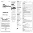
1-7. Replacing the Boards
1-7. Replacing the Boards
n Turn off the power of both power supply units and unplug the power plugs from the outlets before starting the replacement.
1-7-2. Connector Mount
n Be sure to attach IFB shield parts at the top and bottom of a connector panel because they prevent spurious radiation. The connector panel installing procedure depends on the slot number. Use one of the following three types according to the slot number. [Type 1] Slot No.1 [Type 2] Slot No.2,3 [Type 3] Slot No.4 The installation procedures of the three types are explained below. [Type 1] 1. Remove the four screws securing the IFB shield (S1), the IFB shield and the connector panel. 2. Using the four screws that were removed,secure a new connector panel, the IFB shield (S1) and the IFB shield.
1-7-1. The Plug-in Boards
1. Remove the front panel. (Refer to Section 1-2.) 2. Remove the four screws, then remove the BKPF cover.
PSW 3x6
PSW 3x6
BKPF cover
Connector panel PWH 3x6
3. Turn the board lever in the direction of the arrow 2, then pull out the board toward you. 4. Turn the board lever of a new board in the direction of the arrow 1, insert the board along the board guide rail, then push it until it connects to the MB-812 board securely.
IFB shield PWH 3x6 PWH 3x6 IFB shield (S1)
2 1 1 2
[Type 2] 1. Remove the four screws securing the two IFB shields and the connector panel. 2. Using the four screws that were removed, secure a new connector panel and the two IFB shields.
Connector panel PWH 3x6
Board lever
Board lever
1 2
1 2
1 2
Install Remove
IFB shield PWH 3x6
5. Install the BKPF cover and front panel.
PFV-HD50A MM
PWH 3x6
1-5(E)
|
|
|
> |
|