|
|
|
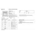
Categories
|
|
Information
|
|
Featured Product
|
|
|
 |
|
|
There are currently no product reviews.
 ;
Detailed schematic diagram, manual for professionals
;
Good service manual,exploded view,adjusment and test point locations,head alignment,mechanical checks and adjusments,all perfect.
;
Block diagram,play rec block diagram,adjusments, it's a very good well done repair manual.
;
Very clear copy of the philips service manual. Fast delivery. Thank you very much
;
Excellent manual, detailed, very useful! Exactly what I needed, I'd recommend it to all who need it. Although images are scanned easily readable and explicit. A valuable tool product at a price more than modest, take it with confidence and you will not regret it!
8. Wiring diagram
Those parts shall be pulled out and left on the outside until the optical unit is mounted.
CNDS1 CNDS2 CNSG
PWB FILTER
ESD2
The wire shall be laid so thatits left-hand side. rib on it passes the Speaker (R)
Top
PWB VIDEO
ESD1
The SK binder screw (SK1) shall be tightened so that the excess binder is located on the backside.
EPOW
There shall be no slack in the wire. PWB R/C
CN1A SP.R
EPOW CNRM LSW2
The CNPOW lead wire shall not run directly over the rib but shall be laid so that it runs around the rib and passes it on its left-hand side. In addition, the height of the lead wire shall not exceed that of the rib. FAN (Power)
CNPOW
Taping (TAPE1) The LSW2 wire shall be secured by means of taping in the vicinity of the screw rib. The wire between the POWER UNIT (CIRCUIT) and PWB FILTER shall be secured by hanging it on the hook of the bottom case.
SP.L
Those parts shall be pulled out and left on the outside until the optical unit is mounted.
CN1B
CN102
There shall be no slack in the wire.
Taping (TAPE4) Speaker L shall be secured in such a way that there is no Screw boss space between the tape/wire and the surface of the board. The wire shall be laid so that it is located under the screw boss. The wire shall be laid so that there shall be no slack, and then Bottom secured. case line The adhesive tape shall be placed directly on the left-hand side of the screw boss and the top of the adhesive tape shall be aligned to that of the screw boss as shown in the figure at the right (which will prevent the wire from getting tangled in the TAPE4 optical unit when mounting it). The wire shall be laid so that the distance between the lower edge of the boss and the wire shall be 5mm or less (the bottom case line shall be used as a reference). Taping (TAPE3) Speaker L shall be secured in such a way that there is no space between the tape/wire and the surface of the board. The adhesive tape shall be placed from the center of the speaker (which will prevent the wire from getting tangled in the optical unit when mounting it). Top
5mm or less
POWER UNIT (CIRCUIT)
CN101
CN101
Speaker (L)
Wiring for Set's Bottom Panel
23
|
|
|
> |
|