|
|
|
Categories
|
|
Information
|
|
Featured Product
|
|
|
 |
|
- SERVICING NOTES
- GENERAL
- DISASSEMBLY
- MECHANICAL ADJUSTMENTS
- ELECTRICAL ADJUSTMENTS
- Tape Deck Section
- Tuner Section
- CD Section
- DIAGRAMS
- Printed Wiring Board - Tuner Section - (PMC - D305)
- Schematic Diagram - Tuner Section - (PMC - D305)
- Schematic Diagram - Tuner Section - (PMC - D305L)
- Printed Wiring Board - Tuner Section - (PMC - D305L)
- Printed Wiring Boards - CD Section
- Schematic Diagram - CD Section
- Printed Wiring Boards - Main Section
- Schematic Diagram - Main Section
- Schematic Diagram - Control Section
- Printed Wiring Boards - Control Section
- Printed Wiring Boards - Power Section
- Schematic Diagram - Power Section
- IC Pin Function Description
- EXPLODED VIEWS
- ELECTRICAL PARTS LIST
There are currently no product reviews.
 ;
Excellent service, and just what I needed to service my TU-7700. All pages of the manual are clear and easily readable.
;
Excellent printing quality.
A complete and very usefull service manual with all details.
GREAT SERVICE AT VERY LOW PRICE!
A+++++++++++++++++++++++++
;
We received the manual in a timely manner and it was exactly what we were expecting. Excellent replacement for original Service Manual.
All schematics are very legible. We are really satisfied.
;
We received the manual in a timely manner and it was exactly what we were expecting. Excellent replacement for original Service Manual.
All schematics are very legible. We are really satisfied.
;
We received the manual in a timely manner and it was exactly what we were expecting. Excellent replacement for original Service Manual.
All schematics are very legible. We are really satisfied.
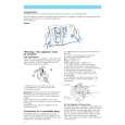
The following is a simple adjustment method. � Simple Adjustment �
Note: Since exact adjustment cannot be performed, remember the positions of the controls before performing the adjustment. If the positions after the primary adjustment are only a little different, return the controls to the original position.
8. Connect the oscilloscope to TP (TRACKING-Y) and TP (VC) on the CD board. 9. Adjust RV704 so that the waveform is as shown in the figure below. (tracking gain adjustment)
VOLT/DIV: 1 V TIME/DIV:2 ms 0V
oscillosope (DC range) CD board TP (FOCUS-Y) TP (TRACKING-Y) TP (VC)
+ �
� Incorrect Examples (fundamental wave appears)
low tracking gain VOLT/DIV: 1 V TIME/DIV: 2ms 0V
Procedure: 1. Keep the set horizontal. If the set is not horizontal, this adjustment cannot be performed 2. 3. 4. 5. due to the gravity against the 2-axis device. Connect the oscilloscope TP (FOCUS-Y) and TP (VC) on the CD board. Insert the disc (YEDS-18) in and close the lid for CD. Put the set into test mode. (See page 30.) Press the ( button. From focus searching, focus is turned ON while entering CLV drawing-in mode. Tracking and sled are turned OFF. 6. Press the ( button. [Both tracking and sled are turned ON.] 7. Adjust RV702 so that the waveform is as shown in the figure below. (Focus gain adjustment)
VOLT/DIV: 100 mV TIME/DIV:2ms 100 mV 0V
high tracking gain high fandamental wave than for low gain VOLT/DIV: 1 V TIME/DIV: 2ms
0V
Note: VOLT/DIV: with the 10:1 probe in used.
10. Release test mode after adjustment is completed. � Inconnect Examples (DC level changes more than on adjusted waveform)
low focus gain VOLT/DIV: 100 mV TIME/DIV:2ms 250 mV 0V
Adjustment Location: CD board (See page 33.)
high focus gain VOLT/DIV: 100 mV TIME/DIV:2ms 100 mV 75 mV 0V
� 32 �
|
|
|
> |
|