|
|
|
Categories
|
|
Information
|
|
Featured Product
|
|
|
 |
|
|
There are currently no product reviews.
 ;
Fast delivery and good quality copy. To be recommended
;
Excellent product, very clear print. Detailed circuit and assembly diagrams - this enabled me to repair my CD player with confidence. I highly recommend this site.
;
Fast access, 100% correct and complete service manual
;
just what i was seeking .had a password issue but the review allowed me to circumvent and download was great
;
Great manual, great price. Has a few of the basic operating instructions that most service manuals leave out. Complete instructions for disassembling board by board, safety precautions, schematics, complete parts list.
Replacement of ICs
1. Using the braided wire, �SOLDER TAUL� (Sony Part No. 7-641-300-81), remove the solder around the pins of the IC-chip to be removed. 2. While heating up the pins, remove the pins one by one using sharp-pointed tweezers. 3. Make sure that there is no pattern peeling, damage and/ or bridge around the desoldering position. 4. After removing the chip part, presolder the area, in which the new chip part is to be placed, with a thin layer of solder. 5. Place new chip part in the desired position and solder the pins.
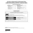
2. Insert the tool tongs into the slots of the carrier socket. Push fully in so that the tool butts on the socket at �A�.
"A"
"A" Chip Carrer (To be removed)
Chip Carrier Socket
4-7-3. Removal of PLCC IC (IC701/DPR-86A Board)
PLCC socket Extraction Tool (Sony Part No. J-6035-070-A) This extraction tool is useful for extracting the IC(PLCC type) inserted into an IC socket, and fits all sizes of ICs from 20 pins through 124 pins.
3. Place the thumb and the first and second finger on the ribbed area of the tool. Maintain a small downwartd force to keep the tool butted on the socket. Squeeze the thumb and finger together so that the tool legs tend to straighten. This action will draw the chip carrier out of the socket and grip it within the tool legs. Maintain the squeezing action so as to hold the chip in the tool, hold the tool over your other hand and relax the squeeze. The chip will fall out of the tool and into your hand.
Finger Thumb Chip Carrier
Chip Carrier Socket
NOTE: Do not try to pull chip carrier out of socket and let the tool action pull it out. Do not squeeze harder than necessary, only enough that the tool action occurs.
<How to use the Extraction Tool>
1. Spread or compress the tool legs so the tongs will fit into the slots of the chip carrier socket.
Hinge Pin Push this Portion
Push this Portion leg
Extraction claw
RSE-500/400 (UC) PMS-500P/400P (CE)
4-19
|
|
|
> |
|