|
|
|
Categories
|
|
Information
|
|
Featured Product
|
|
|
 |
|
|
There are currently no product reviews.
 ;
Great service. Fast response. High quality scan. Good price.
Thank you very much!!!
Oleg S.
;
Well-scanned, complete manual. Contains the information needed for repair and maintenance.
;
It's great to be able to obtain a precious technical information for a real old equipment. The one I got helps me a lot in the area of wiring diagram to repair my antique. PDF gave me clear enough information to find out thr details. Thanks for giving me the oppotunity to be able to access to almost vanished informations.
;
Another excellent aquisition. Fine detailed manual. Thanks
 ;
Good quality for the scan, complete, but as usual for Tascam, not so comprehensive !
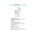
CONNECTION OF SERVICE JIG
SSG2 : SUB
SSG-1 : MAIN
Adjustment point
M-CAN1 Molex04
ANT MAIN ANT SUB
GT13
M5 X 8 mm MAX
PN-2701B-A / PN-2702B-A
VR160 (SUB) VR161 (MAIN)
VR162
ADJUSTMENT
Item FM noise convergence Procedure <MAIN> 1. An antenna input is fixed to a main channel using a jig(Control panel unit). 2. Set an antenna input to main channel. 3. Input the FM 98.1/55dBu(1kHz, 22.5kHz MOD)signal. This state is standard output(=0dB). 4. Adjust VR161 so that the output level becomes -25dB, when set the SSG output is -20dB. <SUB> 1. An antenna input is fixed to a sub channel using a jig(Control panel unit). 2. Set an antenna input to sub channel. 3. Input the FM 98.1/55dBu(1kHz, 22.5kHz MOD)signal. This state is standard output(=0dB). 4. Adjust VR160 so that the output level becomes -20dB, when set the SSG output is -20dB. 1. 2. 3. 4. An antenna input is fixed to a main channel using a jig(Control panel unit). Set an antenna input to main channel. Input the 98.1MHz/55dBu(1kHz, 22.5kHz MOD)signal. Adjust VR162 so that the input level becomes 32dB.
Measuring instrument
SSG Digital tester
FM stop sensitivity
SSG Digital tester
PN-2701B-A PN-2702B-A
-4-
|
|
|
> |
|