|
|
|
Categories
|
|
Information
|
|
Featured Product
|
|
|
 |
|
|
There are currently no product reviews.
 ;
Excellent printing quality.
A complete and very usefull service manual with all details.
GREAT SERVICE AT VERY LOW PRICE!
A+++++++++++++++++++++++++
;
Excellent, very professional, fast, reliable, congratulations thank you.
;
Excellent printing quality.
A complete and very usefull service manual with all details.
GREAT SERVICE AT VERY LOW PRICE!
A+++++++++++++++++++++++++
;
Excellent printing quality.
A complete and very usefull service manual with all details.
GREAT SERVICE AT VERY LOW PRICE!
A+++++++++++++++++++++++++
;
SATELLIT 4000 GRUNDIG
Service Manual
high quality. good graphics. prompt service.
1
2
3
4
A
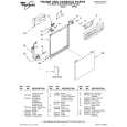
[5] MAIN ASSY
Flowchart of Failure Analysis for The MAIN Assy
Failure analysis for the MAIN Assy => MA1
The STB LED does not light although STB 3.4 V power is supplied.
Does the POWER switch on?
B
No
Turn the POWER switch on.
Yes Is resetting of the IF microcomputer canceled? Yes Is the voltage at Pin 3 of the M11 connector High? Yes Is the M11 connector securely connected? Yes Is the cable that is connected to the M11 connector broken? No No problem with the MAIN Assy. Check the LED Assy. Yes No Securely connect the M11 connector. No Replace the MAIN Assy.
Failure in the line between the IF microcomputer and M11 connector
No
Replace the MAIN Assy.
Failure in the RST IC (IC8302) output or its peripheral circuits
C
Replace the cable (J116).
Failure analysis for the MAIN Assy => MA2
The RELAY port does not work. The power is not turned on.
D
Is the voltage at Pin 50 of the M4 connector 3.4 V? Yes
No
Replace the MAIN Assy.
Relay control is unable unless it supplies a power supply to the module microcompute.
Are the voltages (1.5 V/2.5 V/3.4 V) No supplied to the main microcomputer? Yes Is voltage at REQ_IF on the MAIN Assy High (3.3 V)? Yes
E
Replace the MAIN Assy.
No
Can the unit be turned on, using the remote control unit? Yes
No
Replace the cable (J117) that connects between the IR and MAIN Assys.
NG Replace the IR Assy. NG Replace the MAIN Assy.
Can the unit be turned on, using the Power switch on the unit? Yes
No
Replace the cable (J116) that connects between the SIDE KEY and MAIN Assys.
NG Replace the SIDE KEY Assy. NG Replace the MAIN Assy.
Can the unit be turned on, using RS-232C commands? Replace the MAIN Assy.
F
No
Replace the 50P cable (J213) that NG Replace the IO Assy. connects between the IO and MAIN Assys. NG Replace the MAIN Assy.
58
1 2
PDP-6020FD
3 4
|
|
|
> |
|