|
|
|
Categories
|
|
Information
|
|
Featured Product
|
|
|
 |
|
|
There are currently no product reviews.
 ;
Welcome. The scheme is clearly helped me to repair. Worth to download it.
 ;
Excellent manual, very clear, technical specification provided, useful information regarding adjustment and set up.
;
fast and easy and exactly what I was looking for. Not the cheapest but value for money after all.
;
The manual for the Sansui P-L75 was not one of the more informative turntable manuals around but for $5 it was helpful enough.
;
VERY GOOD SERVICE.FAST ANS VERY HONEST PRICE .RHAANK HERNAN
1
2
3
4
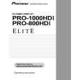
Input Signal Step
A
Adjusting Method
Adjust the black level of the Red and Blue signals referring to that of the Green signal Adjust the signal amplitude of the Red and Blue signals referring to that of the Green signal
Green signal waveform
Green signal waveform
Red or Blue signal waveform
Signal amplitude of the Green signal
Red or Blue signal waveform
B
Black level of the Green signal
Video signal
Black level of the Red or Blue signal
14
C
15
Increase the MAT CONT adjustment value of OFFSET-RGB1 by 3. OFFSET mode: Select RGB 1 mode with the top and bottom keys. MAT CONT : "1" key Increase the adjustment value by 3 with the right and left keys. Increase the MAT BRIGHT adjustment value of OFFSET-RGB1 by 2. OFFSET mode: Select RGB 1 mode with the top and bottom keys. MAT BRIGHT : "2" key Increase the adjustment value by 2 with the right and left keys. Turn the ACL SW setting to ON. INITIALIZE mode ACL SW : "3" key Select ON with the right and left keys. Input a RGB (PC) signal to the INPUT1 or INPUT2. Use a signal consisting of the luminance signal only, such as a ramp signal or STEP signal, whose black level (0IRE) and gradation can be checked. � Recommended signal: VESA VGA@60Hz
16
1
D
2 3 4 RGB (PC) signal 5
Set the unit to Standby mode then to Factory mode. MENU � SET � POWER ON Take a trigger of the oscilloscope with HD_PLL (3.3Vp-p) of K4805. Measure the signal waveform of the Green signal at K4603, and measure the black level (0IRE) and amplitude. AD R LOW adjustment Measure the black level (0IRE) of the Red signal at K4602, and adjust the level of AD R LOW so that its black level (0IRE) becomes the same as that of the Green signal measured in step 9. Tolerance: ± 0.05V OFFSET mode: Select RGB 1 mode with the top and bottom keys. AD R LOW : "9" key Adjust with the right and left keys.
E
6
AD R HIGH adjustment Measure the signal amplitude of the Red signal at K4602, and adjust the level of AD R HIGH so that its signal amplitude becomes the same as that of the Green signal measured in step 9. Tolerance: ± 0.05V OFFSET mode: Select RGB 1 mode with the top and bottom keys. AD R HIGH : "6" key Adjust with the right and left keys.
F
140
1 2
PRO-800HDI
3 4
|
|
|
> |
|