|
|
|
Categories
|
|
Information
|
|
Featured Product
|
|
|
 |
|
|
There are currently no product reviews.
 ;
The manual for Sony LBT-D505 component stereo system is was excellent , with schematics, parts layout and parts list as well as instructions for adjustments for each component. Print was clear even when enlarged.
;
It's exactly a complete and very useful manual with all details what I needed. Thank you!I will come back whenever I need your manuals or schematics.
;
I searched EVERYWHERE looking for the manual/s on this "extinct" amp. Owner-Manuals.com made it available and for nearly nothing. Thanx to them, I can decipher the unknown cables and sort them out. Thanx, Owner-Manuals.com!!
;
Yes thank you i got the file i was after. There was a slight problem in my communication but it all worked out well.
A job well done.
 ;
Great manual...really saved me. The only problem is that I thought I would be able to download it directly when I paid for it but never received the download instructions until the next morning. The board trace pages were somewhat light also: really need to turn up the contrast on the printer before printing them. The schematic page was great; very clear! Well worth the money.
Important safety tests
Measuring H.V.
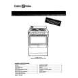
The anode caps are cemented to the CRTs. To gain access for high voltage measurement, remove the red CRT�s anode lead from the flyback transformer distributor. Grasp the anode lead protective cap at its bottom and squeeze it against the locking cap body inside, rotate 1/4 turn counter clockwise and pull the anode lead sleeve out of the FBT distributor. Connect a high voltage lead (+) from your H.V. meter to the FBT distributor, and the common (-) to cold ground ( ). (see figure 2). 1 Grasp protective rubber cap 2 Push & rotate cap counterclockwise to remove Anode lead 3 Discharge to CRT chassis Figure 4. DVM & power supply connection. 5. Connect the 15 ~ 25 V DC variable power supply to (+) TPD8 or IC802 pin 2 (D-Board) and (-) heat sink of Q551 (see figure 4). Procedures: 1. Apply a NTSC white pattern. 2. Turn PTV ON. 3. Adjust the picture or brightness controls so that the DVM reads 16.5 volts ± 0.5 volts. 4. Increase the variable power supply until set turns off. The set should turn off at 16.5 volts ± 0.5 volts (DVM) and high voltage less than 36.4kV. 5. If the DVM reading is other than 16.5 volts ± 0.5 volts, readjust picture or brightness control and repeat steps 3. 6. Turn off the variable supply and confirm that the set will turn on with the remote control. 4. Connect a H.V. meter (static type, class 0.1) with high voltage leads to high voltage distributor on FBT. (See figure 4)
TPD51 TPD50 D-Board
+
-
DVM
MA150 100� 1/2 W
D-Board
IC802 PIN 2 OR TPD8 HEAT SINK OF Q551
(+) Variable power (15~25DC) supply (-)
FBT distributor Figure 2. Removal of FBT leads
Note:
Reinsert the anode lead into the FBT distributor until it is tightly and fully seated. Turn the locking cap clockwise to lock in place.
(EHT) Protector operation check
With the cabinet back removed, apply a nominal 120V AC to the PTV. Over voltage test Preparation: 1. Turn PTV �OFF� 2. Connect a NTSC signal generator to the antenna terminal. 3. Connect DVM (+) TPD50 and (-) TPD51 on D Board (see figure 4) Cold ground
FBT Distributor
+
CRT CHASSIS
H.V. METER
Figure 3. Measuring H.V.
Service Manual
-4-
|
|
|
> |
|