|
|
|
Categories
|
|
Information
|
|
Featured Product
|
|
|
 |
|
|
There are currently no product reviews.
 ;
Good quality, all schematics of few of models. There is also short form of user manual and regulation manual.
;
Perfect copy of the service manual. you can enlarge every page, and it comes up
with all details.
;
It´s very very nice manual with all, what i need. Original in good quality. Very fast business. Very much thanks...
;
Purchased the manual that I was looking for at a great price and could download it easily.. Great service experience and for future purchases I plan to use the site.
Thank you very much
;
Exactly what was needed to assess the product - excellent value and great service
Disassembly for Service
Note:
Board ground wires may have to be disconnected to disassemble some boards. All ground wires must be reconnected using jumper leads, if necessary, before power is applied to PTV for service. 2. Remove (3) screws from around the A/V terminal board (marked with arrows).
Speaker Grille Removal
(Figure 8.) 1. The 2 Speaker Grilles are secured to the wooden base of PTV. Grip each panel from the sides and botton part, gently pull forward to remove. When reassembling, make certain to firmly press on the panel where the insertion points (4) are located, one on each corner. 2. The Center Front Cover is secured by 4 screws.
Panasonic
Front Cover
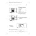
Figure 9. Lower Cabinet Back Removal
Cabinet Back Cover Removal
(Figure 10) 1. First remove the Cabinet Back Lower Cover. 2. The top back cover is secured with (16) screws around its perimeter (See Figure 10 for screws location). 3. Be careful not to damage the mirror attached to the underside of cover.
Speaker Grill
Figure 8. Speaker Grill Removal.
Keyboard Removal (7-Key Button)
(Figure 8) 1. Remove the Speaker Grill. (see Figure 8) 2. Unplug the cables (2) from the Keyboard assembly. Remove the 2 screws from the left and right sides of Keyboard assembly. Tilt the Keyboard assembly upward and release it from the screen frame assembly.
Speakers Replacement
1. Remove the speakers grill. (see Figure 8) 2. Each speaker set is secured to the cabinet with (4) screws. 3. Disconnect the R & L speaker lead connectors from the speaker units.
Cabinet Back Lower Removal
(Figure 9) 1. Remove (7) hex screws around its perimeter marked with arrows. (See Figure 9 for screw location).
Figure 10. Cabinet Back Cover Removal
- 11 -
Service Manual
|
|
|
> |
|