|
|
|
Categories
|
|
Information
|
|
Featured Product
|
|
|
 |
|
|
There are currently no product reviews.
 ;
Super manual it contains all the things you need to service your Marantz 2100.
;
A very easy to understand and use manual. Well worth the money.
 ;
Very good information with clear drawings. Thanks!
;
The ease of this purchase was a good start. The content of this manual was exactly all I needed to retore my Tandberg 64.
All of the mechanical and electrical information is contained in the manual and the quality of the document makes reading the data easy.
The exerience with the resource has made this my prime source for technical data.
;
Owner-manuals.com is the best Possibility to give vantage HIGH CLASS Elektronic COMPONENTS
a new Life.Thanks alot for your perfekt Service.
Disassembly for Service
Note:
Board ground wires may have to be disconnected to disassemble some boards. All ground wires must be reconnected using jumper leads, if necessary, before power is applied to PTV for service. 2. Remove (3) screws from around the A/V terminal board (marked with arrows).
Speaker Grille Removal
(Figure 8.) 1. The 2 Speaker Grilles are secured to the wooden base of PTV. Grip each panel from the sides and botton part, gently pull forward to remove. When reassembling, make certain to firmly press on the panel where the insertion points (4) are located, one on each corner. 2. The Center Front Cover is secured by 4 screws.
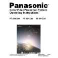
Panasonic
Front Cover
Figure 9. Lower Cabinet Back Removal
Cabinet Back Cover Removal
(Figure 10) 1. First remove the Cabinet Back Lower Cover. 2. The top back cover is secured with (16) screws around its perimeter (See Figure 10 for screws location). 3. Be careful not to damage the mirror attached to the underside of cover.
Speaker Grill
Figure 8. Speaker Grill Removal.
Keyboard Removal (7-Key Button)
(Figure 8) 1. Remove the Speaker Grill. (see Figure 8) 2. Unplug the cables (2) from the Keyboard assembly. Remove the 2 screws from the left and right sides of Keyboard assembly. Tilt the Keyboard assembly upward and release it from the screen frame assembly.
Speakers Replacement
1. Remove the speakers grill. (see Figure 8) 2. Each speaker set is secured to the cabinet with (4) screws. 3. Disconnect the R & L speaker lead connectors from the speaker units.
Cabinet Back Lower Removal
(Figure 9) 1. Remove (7) hex screws around its perimeter marked with arrows. (See Figure 9 for screw location).
Figure 10. Cabinet Back Cover Removal
- 11 -
Service Manual
|
|
|
> |
|