|
There are currently no product reviews.
 ;
The schematic is very helpful and the images are very good.The schematic is very helpful and the images are very good.The schematic is very helpful and the images are very good.The schematic is very helpful and the images are very good.The schematic is very helpful and the images are very good.The schematic is very helpful and the images are very good.
;
Welcome. The scheme is clearly helped me to repair. Worth to download it.
 ;
Excellent manual, very clear, technical specification provided, useful information regarding adjustment and set up.
;
fast and easy and exactly what I was looking for. Not the cheapest but value for money after all.
;
The manual for the Sansui P-L75 was not one of the more informative turntable manuals around but for $5 it was helpful enough.
Rear support plate removal
3. Remove four screws as shown. Two behind the metal sheet, one between ballast and fan, and one under the ballast.
Lamp Connector
8. The optical block is shown below.
Optical block screw location
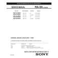
4. Unplug L1 connector. 5. Open the front SD card door before to take optical block out, to avoid door from getting stock 6. Lift the upper cabinet, then take the optical block out by pulling out, up and out as shown. NOTE: Do not take out the optical block completely, there is the lamp connector behind that must be unplugged.
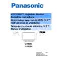
10.2. L-Board Removal
1. Remove the three screws that holds the board.
Optical block pull out
7. Unplug the lamp connector shown inside the white circle. Then take the optical block out completely.
2. When placing this board, do not tight completely the three screws shown on above picture, first move the board right/left and up/down to center the image on the screen, then when best overall image centering is obtained, tight the screws. NOTE: Position of L-Board is critical to the raster position. If the black screws are not removed, the L-Board will keep its position. However, if they are removed, raster position must 18
|