|
|
|
Categories
|
|
Information
|
|
Featured Product
|
|
|
 |
|
|
There are currently no product reviews.
 ;
I PURHASED THIS PRODUCT BECAUSE I WAS HAVING PROBLEMS WITH MY CDR20 HARMAN KARDON RECORDER. WHICH I PURCHASED NEW 12 YEARS AGO. AFTER REVIEWING THE MANUAL, I WAS ABLE TO ADJUST THE TENSIONER IN THE SYSTEM. WORKS LIKE A CHAMP!.
SAVED ME AT LEAST 100.00 WHICH WAS WHAT A SERVICE REPAIR STATION WANTED. GREAT MANUAL EASY TO READ. SPECIALLY AFTER I PRINTED THE PAGES WHICH DEALT WITH MY RECORDER. THANKS A LOT!!!!!!!!
 ;
You can fully trust on this one!
All the schematics are very crear an in one piece per page
;
I have never bought a service manual which is as competely readable as this althogh it was a scanned pdf. Thank you for this succesful manual also cheaper than other sites.
;
Thanks for a very good and readable servicemanual. Just what I needed as a "dinosaur technician". I really recommmend this site and will come back.
Åsbjörn
;
The manual I purchased was just what I needed. I was glad to find a site where I can find so many manuals on a wide variety of products.
PT-LB20NTU / PT-LB20NTE / PT-LB20NTEA / PT-LB20U / PT-LB20E / PT-LB20EA / PT-LB20SU / PT-LB20SE / PT-LB20SEA / PT-LB20VU / PT-LB20VE / PT-LB20VEA
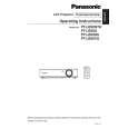
7.4.
Removal of WL-P.C.Board (PTLB20NTU/E/EA only)
1. Remove the upper case according to the section 7.2. "Removal of Upper Case". 2. Unscrew the 4 screws and remove the shield cover and wireless LAN module. Notes: · Because the wireless LAN module is connected with the WL-P.C.Board, work carefully when removing it. · When installing/detaching the antenna connector, insert or pull out it straight along the center of the connector pin. It causes damage and/or poor contacting of the connector when forcibly installing/detaching it. · Connect the connector from the antenna with the original position (connector on the wireless LAN module) after reassembling. 3. Unscrew the 1 screw and remove the WL-P.C.Board.
7.6.
Removal of S2-P.C.Board
1. Remove the S2-P.C.Board block according to the section 7.3. "Removal of A-P.C.Board". 2. Remove the holder while expanding the resin hooks outside. Note: · Work carefully not to damage the resin hook.
7.7.
Removal of K-P.C.Board
1. Remove the analysis block, LCD block and lens according to the steps 1 through 3 in the section 7.11. "Removal of Analysis Block and Lens". 2. For PT-LB20NTU/E/EA, unscrew the 4 screws and remove the shield cover and wireless LAN module.
7.5.
Removal of S1-P.C.Board
1. Remove the upper case according to the section 7.2. "Removal of Upper Case". 2. Remove the water-guide plate.
Notes: · Because the wireless LAN module is connected with the WL-P.C.Board, work carefully when removing it. · When installing/detaching the antenna connector, insert or pull out it straight along the center of the connector pin. It causes damage and/or poor contacting of the connector when forcibly installing/detaching it. · Connect the connector from the antenna with the original position (connector on the wireless LAN module) after reassembling. 3. For PT-LB20NTU/E/EA, unscrew the 2 screws and remove the WL-P.C.Board (with metal fittings for securing WL).
3. Unscrew the 2 screws and remove the S1-P.C.Board.
17
|
|
|
> |
|