|
|
|
Categories
|
|
Information
|
|
Featured Product
|
|
|
 |
|
|
There are currently no product reviews.
 ;
Excellent manual, detailed, very useful! Exactly what I needed, I'd recommend it to all who need it. Although images are scanned easily readable and explicit. A valuable tool product at a price more than modest, take it with confidence and you will not regret it!
;
Clear and complete service manual. Easy now to restore my old Kenwood KD-1500.
Thanks a lot.
;
Thanks for this "hard to find" service manual. This Sony PS212A is a very good turntable that needed to be restored !
 ;
Excellent quality on these manuals. Same as having the original printed manual and incredibly useful when doing a custom install like me. Keep it up on the good work.
;
This is an excellent information source. Great quality and tons of info regarding technical service for the Technics SH8065.
PT-LB30NTU / PT-LB30NTE / PT-LB30NTEA / PT-LB30U / PT-LB30E / PT-LB30EA
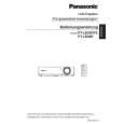
5. Unscrew the 4 screws and remove the power block (PModule and B/Q-Module).
6. Unscrew the 3 screws and remove the power box.
7.8.
Removal of G-P.C.Board
1. Remove the A-P.C.Board block according to the steps 1 through 6 in the section 7.3. "Removal of A-P.C.Board". 2. Disconnect the flexible cable between the G-P.C.Board and A-P.C.Board. 3. Unscrew the 2 screws and remove the G-P.C.Board. 7. While pressing to shut each hook of the 4 resinous stands, remove the B/Q-Module.
7.9.
Removal of B/Q-Module
1. Remove the lamp unit according to the section 7.11. "Removal of Lamp Unit". 2. Remove the A-P.C.Board block according to the steps 1 through 6 in the section 7.3. "Removal of A-P.C.Board". 3. Unscrew the 2 screws and remove the lamp unit terminal. 4. Unscrew the 2 screws and remove the exhaust fan .
7.10. Removal of P-Module
1. Remove the power block and power box according to the steps 1 through 6 in the section 7.9. "Removal of B/Q Module". 2. Unscrew the 1 screw. 3. While pressing to shut each hook of the 3 resinous stands, remove the P-Module.
18
|
|
|
> |
|