|
|
|
Categories
|
|
Information
|
|
Featured Product
|
|
|
 |
|
|
There are currently no product reviews.
 ;
exactly as they say. Within 24 hours the link to the pages and offcourse it was the right service manual. Super and thanks
 ;
The manual was exact the thing that was promised. My old car stereo is working again thanks to the information supplied.
;
I PURHASED THIS PRODUCT BECAUSE I WAS HAVING PROBLEMS WITH MY CDR20 HARMAN KARDON RECORDER. WHICH I PURCHASED NEW 12 YEARS AGO. AFTER REVIEWING THE MANUAL, I WAS ABLE TO ADJUST THE TENSIONER IN THE SYSTEM. WORKS LIKE A CHAMP!.
SAVED ME AT LEAST 100.00 WHICH WAS WHAT A SERVICE REPAIR STATION WANTED. GREAT MANUAL EASY TO READ. SPECIALLY AFTER I PRINTED THE PAGES WHICH DEALT WITH MY RECORDER. THANKS A LOT!!!!!!!!
;
You can fully trust on this one!
All the schematics are very crear an in one piece per page
;
I have never bought a service manual which is as competely readable as this althogh it was a scanned pdf. Thank you for this succesful manual also cheaper than other sites.
PT-LB30NTU / PT-LB30NTE / PT-LB30NTEA / PT-LB30U / PT-LB30E / PT-LB30EA
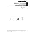
5. Unscrew the 4 screws and remove the power block (PModule and B/Q-Module).
6. Unscrew the 3 screws and remove the power box.
7.8.
Removal of G-P.C.Board
1. Remove the A-P.C.Board block according to the steps 1 through 6 in the section 7.3. "Removal of A-P.C.Board". 2. Disconnect the flexible cable between the G-P.C.Board and A-P.C.Board. 3. Unscrew the 2 screws and remove the G-P.C.Board. 7. While pressing to shut each hook of the 4 resinous stands, remove the B/Q-Module.
7.9.
Removal of B/Q-Module
1. Remove the lamp unit according to the section 7.11. "Removal of Lamp Unit". 2. Remove the A-P.C.Board block according to the steps 1 through 6 in the section 7.3. "Removal of A-P.C.Board". 3. Unscrew the 2 screws and remove the lamp unit terminal. 4. Unscrew the 2 screws and remove the exhaust fan .
7.10. Removal of P-Module
1. Remove the power block and power box according to the steps 1 through 6 in the section 7.9. "Removal of B/Q Module". 2. Unscrew the 1 screw. 3. While pressing to shut each hook of the 3 resinous stands, remove the P-Module.
18
|
|
|
> |
|