|
|
|
Categories
|
|
Information
|
|
Featured Product
|
|
|
 |
|
|
There are currently no product reviews.
 ;
Thank you very much, I've been very happy to find this manual on "Owner Manual". It's a perfect copy and it has been really useful for my work!
;
It took about 24-hours after my payment before I was able to get to the download. Apparently, payment processing is not 100% automated. That is no big deal, just be aware of that going in.
After I got to it, it was in good shape, easy to read, etc. Not some cheap FAX copy looking thing.
Also, this site was the cheapest I found. Another Plus!
 ;
Good price, very legible manual, exactly what I needed -- but had to wait a day to actually get the download of the manual. Would have preferred to download it immediately after payment rather than waiting for someone to "process" my order. I was surprised that I had to wait that long.
;
As the only source for this manual it rather rank quite high since it is well scanned and perfectly readable.
;
the manual is in good quality and it's in pdf. manual was send in less then 24h.
regards
mike
PT-LB50NTU / PT-LB50NTE / PT-LB50NTEA / PT-LB50U / PT-LB50E / PT-LB50EA / PT-LB50SU / PT-LB50SE / PT-LB50SEA
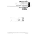
7.2.
Removal of Upper Case
1. Turn the projector upside down. 2. Unscrew the 6 screws.
7.4.
Removal of G-P.C.Board
1. Remove the connector metal fittings with the G-P.C.Board according to the section 7.3. "Removal of A-P.C.Board". 2. Unscrew the 1 screw and remove the G-P.C.Board .
3. Return the projector to the normal position. 4. Remove the upper case.
7.3.
Removal of A-P.C.Board
1. Remove the upper case according to the section 7.2. "Removal of Upper Case". 2. Unscrew the 2 screws and remove the lamp house. 3. Unscrew the 1 screw and remove the connector cover 4. Unscrew the 3 screws fixing the S-P.C.Board. 5. Unscrew the 3 screws fixing the A-P.C.Board.
7.5.
Removal of S-P.C.Board
1. Remove the upper case according to the section 7.2. "Removal of Upper Case". 2. Unscrew the 3 screws. 3. Disconnect the flexible cable and remove the S-P.C.Board.
6. Disconnect the connectors from/to the A-P.C.Board, then remove the A-P.C.Board block with the G-P.C.Board and SP.C.Board. 7. Unscrew the 8 screws and remove the connector metal fittings. Note: · The G-P.C.Board is attached on the connector metal fittings, and it is connected with the A-P.C.Board. Work carefully when removing the connector metal fittings.
7.6.
Removal of WL-P.C.Board (PTLB50NTU/E/EA only)
1. Remove the upper case according to the section 7.2. "Removal of Upper Case". 2. Unscrew the 3 screws and remove the WL-P.C.Board with wireless LAN module.
16
|
|
|
> |
|