|
|
|
Categories
|
|
Information
|
|
Featured Product
|
|
|
 |
|
|
There are currently no product reviews.
 ;
It was complete service manual with all needed service informations. Thanks.
 ;
El manual esta muy detallado, los numeros de partes y los esquemas de despiece son correctísimos y muy claros, tanto para los técnicos experimentados como para los novatos.
;
Ottima qualità grafica e completo nelle notizie. Costo abbastanza contenuto.
;
Great and quick support. The maual was exactly what I was looking for and my problem
solved. Many thanks.
;
Very good service Within one day i received a pdf of the users manual and electric circuits so I was able to measure the different voltages in the printed circuit and find out the fault Payment was also reliable and easy.Without the manual i could not have repaired.So thanks to "Search for a manual"
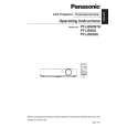
PT-LB50NTU / PT-LB50NTE / PT-LB50NTEA / PT-LB50U / PT-LB50E / PT-LB50EA / PT-LB50SU / PT-LB50SE / PT-LB50SEA
7.2.
Removal of Upper Case
1. Turn the projector upside down. 2. Unscrew the 6 screws.
7.4.
Removal of G-P.C.Board
1. Remove the connector metal fittings with the G-P.C.Board according to the section 7.3. "Removal of A-P.C.Board". 2. Unscrew the 1 screw and remove the G-P.C.Board .
3. Return the projector to the normal position. 4. Remove the upper case.
7.3.
Removal of A-P.C.Board
1. Remove the upper case according to the section 7.2. "Removal of Upper Case". 2. Unscrew the 2 screws and remove the lamp house. 3. Unscrew the 1 screw and remove the connector cover 4. Unscrew the 3 screws fixing the S-P.C.Board. 5. Unscrew the 3 screws fixing the A-P.C.Board.
7.5.
Removal of S-P.C.Board
1. Remove the upper case according to the section 7.2. "Removal of Upper Case". 2. Unscrew the 3 screws. 3. Disconnect the flexible cable and remove the S-P.C.Board.
6. Disconnect the connectors from/to the A-P.C.Board, then remove the A-P.C.Board block with the G-P.C.Board and SP.C.Board. 7. Unscrew the 8 screws and remove the connector metal fittings. Note: · The G-P.C.Board is attached on the connector metal fittings, and it is connected with the A-P.C.Board. Work carefully when removing the connector metal fittings.
7.6.
Removal of WL-P.C.Board (PTLB50NTU/E/EA only)
1. Remove the upper case according to the section 7.2. "Removal of Upper Case". 2. Unscrew the 3 screws and remove the WL-P.C.Board with wireless LAN module.
16
|
|
|
> |
|