|
|
|
Categories
|
|
Information
|
|
Featured Product
|
|
|
 |
|
|
There are currently no product reviews.
 ;
El producto satisface las necesidades del servicio t
;
This is a good quality scan of the Operation & Maintenance (Service) Manual for the PAL version of this high-band broadcast umatic, BVU-800P
All schematics and lineup procedures appear to be included in this one manual AFAICT.
The file size is just over 113 MB which gives an idea of the quality and number of pages.
All of the schematics, which contain some fairly small print, are easily readable when you zoom into the page.
John Thompson, Newcastle Upon Tyne, England.
;
Good quality, all schematics of few of models. There is also short form of user manual and regulation manual.
;
Perfect copy of the service manual. you can enlarge every page, and it comes up
with all details.
;
It´s very very nice manual with all, what i need. Original in good quality. Very fast business. Very much thanks...
5. A/C HEAD HORIZONTAL POSITION ADJUSTMENT
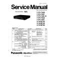
Purpose: To adjust the Horizontal Position of the A/C Head. Symptom of Misadjustment: If the Horizontal Position of the A/C Head is not properly adjusted, a maximum envelope cannot be obtained at the Neutral Position of the Tracking Control Circuit. Place a jumper between TP6003 on the Video Signal Process Section and +5V(TP6009) on the System Control Section of the Main C.B.A. to defeat Auto Tracking. 1. Eject the tape and insert it again to access the Neutral Tracking position. Connect the oscilloscope to TP3002 on the Video Signal Process Section of the Main C.B.A. Use TP6205 as a trigger. 2. Play back the alignment tape and confirm that the RF envelope appears. 3. If adjustment is required, loosen the Black Screw (D) and tighten it lightly. Set the H-Position Adjustment Driver into the Hole (A). Then slowly turn the fixture either clockwise or counterclockwise so that the envelope is at maximum. 4. Before finding the center of the maximum period of the envelope, rotate the fixture back and forth slightly to confirm the limits on either side of the maximum period. 5. Push the Tracking Control Up Button (on the Remote Control) several times (count the number of times pushed) until the maximum envelope is reduced to 1/2. 6. Reset the tracking to the neutral position by ejecting the tape and reinserting it. Push the Tracking Control Down Button (on the Remote Control) several times (count the number of times pushed) until the maximum envelope is reduced to 1/2. 7. If the number of pushing is not the same, then loosen the Black Screw (D) and set the H-Position Adjustment Driver into the Hole (A) to find the center point. Then repeat the above procedure to determine the center point. 8. Tighten Black Screw (D). 9. Remove the jumper between TP6003 and +5V(TP6009).
Black Screw (D)
Hole (A)
Fig. M11 Note: Old type of H-Position Adjustment Driver (VFK0136) can be used for this adjustment.
2-23
|
|
|
> |
|