|
|
|
Categories
|
|
Information
|
|
Featured Product
|
|
|
 |
|
|
There are currently no product reviews.
 ;
Excellent printing quality.
A complete and very usefull service manual with all details.
GREAT SERVICE AT VERY LOW PRICE!
A++
;
Excellent printing quality.
A complete and very usefull service manual with all details.
GREAT SERVICE AT VERY LOW PRICE!
A++
;
Excellent printing quality.
A complete and very usefull service manual with all details.
GREAT SERVICE AT VERY LOW PRICE!
A++
;
Excellent printing quality.
A complete and very usefull service manual with all details.
GREAT SERVICE AT VERY LOW PRICE!
A++
;
Excellent printing quality.
A complete and very usefull service manual with all details.
GREAT SERVICE AT VERY LOW PRICE!
A+
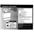
6. Envelope Adjustment
Note: This adjustment is required when the indicator color becomes red in �step 10� of �4. Getting Start.� If it becomes blue, this adjustment need not to be performed. Purpose: To make sure that the tape path is well stabilized. Symptom of Misadjustment: If the tape travels with instability, it may damage the tape.
Adjustment Procedure
1) Display the adjustment menu. (Refer to 4. Getting Start) 2) Remove Screw B, Screw C and remove the Left Cover.
Left Cover Screw B Screw C
3) Connect the oscilloscope to Envelope TP on the Interface Board. (Use HID on the Interface Board as a trigger.) 4) Adjust the S1 post by turning the top of post with Post Height Adjustment Fixture(VFK1278) so that the left half of envelope signal becomes flat as possible. 5) Adjust the T1 post by turning the top of post with Post Height Adjustment Fixture(VFK1278) so that the right half of envelope signal becomes flat as possible.
POST HEIGHT ADJUSTMENT FIXTURE (VFK1278)
T1 POST
S1 POST
3-20
|
|
|
> |
|