|
|
|
Categories
|
|
Information
|
|
Featured Product
|
|
|
 |
|
|
There are currently no product reviews.
 ;
I was having a hard time finding the problem with this Mackie 1604 unit. I didn't have a schematic. Went looking on the web and found your site and the price was more then reasonable. Ordered it and within the hour had the manual and within 15 minutes had the unit fixed. Best $4.99 I ever spent. Thank you.
Doug
;
This is a service manual in every sense of the word ( French and German versions of the text are included, as well as English..)
There are explanations of the mechanical and electrical functions, plenty of mechanical drawings, and the needed schematics. The quality of the scanning is excellent - all the component values are clearly legible - and very usefully there are pcb component layouts, so you can find a component on the schematic, and then very quicky pinpoint its physical location on the relevant pcb.
I cannot see how I can give this manual any less than the maximum 5 stars! Great value for money, which will pay for itself immediately. Excellent all round!
;
the manual is great and especially hard to find... thanks for the great service and having a hard to find manuel_
;
Please tell us what you think and share your opinions with others. Be sure to focus your comments on the product. You will receive $2.50 of store credit for Your review.
;
hat alles sehr gut geklappt. Das Servicemaual ist gut zu verwenden. Die Pläne und Schrift
ist klar und leserlich. Außerdem preiswert. Grüße an alle Hifi-Bastler
PV-GS29P / PV-GS36P / PV-GS39P / PV-GS59P / PV-GS29PC / PV-GS39PC / PV-GS59PC
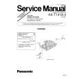
9. Removal of Cassette Cover Unit 1) Remove the 3 Screws (519). 2) Disconnect the F.P.C. from Connector FP7001. 3) Pull off the Mechanism Ass'y & Main P.C.B.
519
Replacement of Mechanism Chassis Ass'y When replacing the Main Chassis Ass'y or the Cylinder Unit, be sure to perform the Envelope Output Adjustment. Refer to "ENVELOPE OUTPUT ADJUSTMENT" in MECHANICAL ADJUSTMENT. Mechanism Chassis Ass'y Handling Caution When servicing the Mechanism Chassis Ass'y without the Cassette Up Unit, do not handle the Sub Chassis of the Mechanism Chassis Ass'y.
Mechanism Chassis Ass'y (without Cassette Up Unit) Sub Chassis
Cassette Cover Unit
519
FP7001
519
Fig. D10 10. Installation of Main P.C.B. Take care not to damage the F.P.C.s. 1) Connect the F.P.C.s to the connectors on the Main P.C.B., verifying that the direction of the Flexible Cables is correct. Refer to "REMOVAL/INSTALLATION OF F.P.C. FROM NON ZIF (Zero Insertion Force) CONNECTOR." 2) Tighten the 2 Screws (545). 3) After installing the Main P.C.B, confirm the F.P.C.s are positioned as shown.
Sub Chassis
Main P.C.B.
545
Sub Chassis
<Side View> Fig. D11-2
545
Mechanism Chassis Ass'y
Capstan Sub Mechanism Cylinder Head F.P.C. F.P.C. F.P.C. Mechanism Amp F.P.C. F.P.C.
57
|
|
|
> |
|