|
|
|
Categories
|
|
Information
|
|
Featured Product
|
|
|
 |
|
|
There are currently no product reviews.
 ;
Very good product. Best service manual. Many thanks
;
I am only search for 5 Minute, by it in 5 Minutes to and get ist in few ours! Best i found in the Internet and my Amplifer is repaired as well! Thank you
 ;
Readable text and good copy. Very much needed if you wish to do some repairs on this fine old unit.
;
Fint forløb med levering af manualen. Kvaliteten af skanningen betegnes som middel
;
I found the manual to be clear concise and complete. It was of immense assistance when removing the unit as the unit was over 22 years old and the wiring diagram was unobtainable from the manufacturer. The exploded drawings were clear as were the instructions and labels.
PV-GS29P / PV-GS36P / PV-GS39P / PV-GS59P / PV-GS29PC / PV-GS39PC / PV-GS59PC
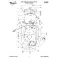
9. Removal of Cassette Cover Unit 1) Remove the 3 Screws (519). 2) Disconnect the F.P.C. from Connector FP7001. 3) Pull off the Mechanism Ass'y & Main P.C.B.
519
Replacement of Mechanism Chassis Ass'y When replacing the Main Chassis Ass'y or the Cylinder Unit, be sure to perform the Envelope Output Adjustment. Refer to "ENVELOPE OUTPUT ADJUSTMENT" in MECHANICAL ADJUSTMENT. Mechanism Chassis Ass'y Handling Caution When servicing the Mechanism Chassis Ass'y without the Cassette Up Unit, do not handle the Sub Chassis of the Mechanism Chassis Ass'y.
Mechanism Chassis Ass'y (without Cassette Up Unit) Sub Chassis
Cassette Cover Unit
519
FP7001
519
Fig. D10 10. Installation of Main P.C.B. Take care not to damage the F.P.C.s. 1) Connect the F.P.C.s to the connectors on the Main P.C.B., verifying that the direction of the Flexible Cables is correct. Refer to "REMOVAL/INSTALLATION OF F.P.C. FROM NON ZIF (Zero Insertion Force) CONNECTOR." 2) Tighten the 2 Screws (545). 3) After installing the Main P.C.B, confirm the F.P.C.s are positioned as shown.
Sub Chassis
Main P.C.B.
545
Sub Chassis
<Side View> Fig. D11-2
545
Mechanism Chassis Ass'y
Capstan Sub Mechanism Cylinder Head F.P.C. F.P.C. F.P.C. Mechanism Amp F.P.C. F.P.C.
57
|
|
|
> |
|