|
|
|
Categories
|
|
Information
|
|
Featured Product
|
|
|
 |
|
|
There are currently no product reviews.
 ;
Excellent quality service manual. Quick processing, fair prices. Love to do business again. Thank you!!!
;
Excellent service manual, the only known point of note is the alignment of improvability scanned pages within the pdf page. The resolution is good.
;
I was very glad recieving the service manal from You. Additionaly very fast. Extremaly nice servicing. Thanks very mach! Now my GX-220 working better, than it was made. Alexander from Moscow, Russia/
;
Sweet! I won the item on eBay and couldn't adjust the geometry or even keep a steady picure. This guide has the full schematics (not available anywhere else as far as I could tell), and was a bargain for the wealth of knowledge it contains. I hooked it up to my testing equipment, tweaked a few potentiometers and got it playing videogames in no time. Thanks!
;
It was just what I need to fix my old BMW's CD player. Very convenient also. Thank you.
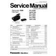
PV-D300 / VM-D100 / PV-L550 / PV-L600 / PV-L650 / VM-L450
5.1.7.
CAUTION:
HOW TO REMOVE A JAMMED TAPE
If loading does not start after DC Power Supply is applied, DO NOT continue applying DC Power Supply.
5.1.7.1.
Remove a jammed tape as follows:
1. Remove a Screw and remove the EVR Cover.
Fig. 4-2
5. Open the Cassette Cover fully.
Fig. 4-1
6. Remove the tape slack by rotating the Takeup Reel Gear of the cassette tape as shown in Fig. 4-3.
2. Place the unit with the Cassette Cover facing upward. 3. Connect the TP Board Kit through the TP Board slot. 4. Apply +3VDC Power Supply to TP20 (+) and TP21 (-) on the TP Board to unload the mechanism. It normally takes approx. 6 seconds to unload the Mechanism to EJECT position. Then, remove the Power Supply and remove the TP Board Kit.
Fig. 4-3
7. Take out the cassette tape. 8. Connect the Power or Battery to set the Mechanism to STOP Position.
20
|
|
|
> |
|