|
|
|
Categories
|
|
Information
|
|
Featured Product
|
|
|
 |
|
|
There are currently no product reviews.
 ;
Very easy site. Great service and quick release for download. Manuals are of good quality.
Joop - The Netherlands
;
Very good manual, in depth and complete. Only criticism is that some of the circuit diagrams are slightly blurry and hard to follow for long periods of time, but this is to be expected. Perfect for any maintenance required. Also contains the wiring diagrams of the control cable for constructing extensions.
;
Received a quick response, material was exactly what it was supposed to be. The service did everything I expected it to do. would use service again.
;
Detailed SONY CFD980 Service Manual at an easy to find one stop shopping. Make my radio hobby technically interesting. Thanks.
 ;
Excellent service from Owner-Manuals.com, good prices and quick turn around. The supplied PDF was good enough quality to be enlarged sufficiently to read component values.
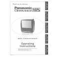
Main Cam Gear and Drive Rack Arm
Disassembly Procedure
1. 2. 3. 4. Remove the Main Cam Push Nut. (Refer to Note.) Pull up on the Main Cam Gear. Turn the Drive Rack Arm fully counterclockwise as shown. Pull up on the Drive Rack Arm.
Reassembly Notes
1. Alignment of Main Cam Gear and Drive Rack Arm 1) Install the Drive Rack Arm so that the hole (A) is aligned with the hole on chassis as shown (Through hole (A)). 2) Install the Main Cam Gear so that the 2 holes (B) marked "E" are aligned with the hole on chassis as shown (Through hole (B)). ("E" indicates the EJECT position.)
Chassis Hole 7 Main Cam Gear 8 Drive Rack Arm turn Main Cam Gear Chassis Hole
E
mark Chassis Through Holes (B)
Drive Rack Arm Through Hole (A)
Fig. J5-3
Main Cam Push Nut
Fig. J5-1 Note: When removing the Main Cam Push Nut, use a screwdriver etc. Shaft of Main Cam Gear Main Cam Push Nut Bottom of Chassis
2. Installation of Main Cam Gear and Main Cam Push Nut 1) Position the chassis upside down placing a Support under the Main Cam Gear. Install the Main Cam Push Nut with Needlenose Pliers etc. so that it is flush with the chassis. There may be some slight scratches on the Shaft of Main Cam Gear, when removing the Main Cam Gear. In case that the Main Cam Gear can be installed securely without tottering, it is fine to use the one. If any tottering, replace a new one.
Press Needlenose Pliers Shaft of Main Cam Gear
Screwdriver
Bottom of Chassis
Main Cam Push Nut Main Cam Gear
Main Cam Gear support Fig. J5-2 Fig. J5-4 3. Main Cam Push Nut is not reusable. If removed, install a new one.
2-10
|
|
|
> |
|