|
|
|
Categories
|
|
Information
|
|
Featured Product
|
|
|
 |
|
|
There are currently no product reviews.
 ;
This service manual was determinant to enable to fix my Alpine Amplifier. I am pleased with my purchase. For a 5 star rating I would like to see a higher resolution scan of the printed circuit board lay-out because the gray scale grafics was dificult to see. Also some schematic diagrams were scanned at a slight angle. Never the less, it had all information I needed to troubleshoot and service my equipment.
 ;
Complete manual, the good quality of reproduction allows enlarged print-out of the schematic diagram in the size it probably had in the original print edition and which is necessary for practical use.
;
The service manual was complete and the components on the drawings very good visible.
;
downloaded next day , manual is very helpful , fast and easy
;
This Service Manual was exactly what I needed to repair my Philips TV. The purchase was convenient and I received the manual at the same day I paid for it.
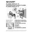
PZ-43MR2E PZ-50MR2E
» IC405/IC402 (CXD2064Q) This IC is a comb filter in the applicable field for both the NTSC and PAL systems. It performs the Y/C separation of the main and sub channel video signals that have been output from IC1801. » IC407/IC404 (ML6428C1) This IC is a 6.7 MHz low-pass filter. » IC810/IC804 (IX3473CE) This IC is a 6.7 MHz low-pass filter incorporating a 6 dB amplifier. » IC811 (IX3474CE) This IC is a 30 MHz low-pass filter incorporating a 6 dB amplifier. » IC1702 (FA3675CE) This IC is designed to control the 6-channel PWM switching regulator. With 5 step-up switching regulator lines incorporated, the IC converts +10V to +2.5V, +3.3V and +5.8V. Also with a step-down switching regulator line incorporated, the IC converts +10V to +6.0V, -5.0V, +12V and +35V. The lines are individually turned on and off. � Description of Functions of Main ICs on PC I/F Unit » IC4 (CXA3506R) This IC is an A/D converter that incorporates a 3-channel, 8-bit, 120 MSPS amplifier and PLL. It is used for the video signals input to the PC I/F unit on the main channel in the 1-screen and 2-screen modes, and also for the video signals input from the front for the PC. The video signals (analog RGB) from the CN6 are input to IN1 of IC4. For the PC, the video signals (analog RGB) from CN8 are input to IN2 of IC4. The input video signals are converted into digital signals and then sent to IC25. » IC310 (TLC5733A) This IC is a 3-channel, 8-bit, 20 MSPS A/D converter. It is used for the sub-channel of the video signals input to the PC I/F Unit in the 2-screen mode. The video signals (analog Y, Cb, Cr) from CN6 are input to IC310. The video signals input to this IC are converted into digital signals and then sent to IC25. » IC25 (IX3434CE) This IC performs the I/P conversion and scaling to match the digitalized video with the output resolution, and also the data conversion. It has two input lines, V0 and V1. The V0 line is used to process the RGB, composite, and skirt signals input to the 480i and 580i components for the sub-channel in the 2-screen mode. The V1 line is used to process all the signals as well as V1 for the main channel in the 1-screen and 2-screen modes. The IC25 detects what resolution is input from the input synchronizing signal; creates H synchronization in accordance with the frequency division ratio; creates the clamp signal in accordance with the input synchronizing signal; and performs the data matrix conversion. The video signals input to this IC is sent to IC413. » IC413 (SiI168) This IC is a panel link transmitter. It converts the 8-bit RGB video data output from IC25 into the differential TMDS signals and then digitally transmits the converted signals to the monitor. The TMDS signals are transmitted at the frequency 10 times higher than the clock frequency. » IC1 (IX3270CE) This IC is a 1-chip RISC microprocessor. It performs communication with the monitor and operates the system. The IC1 also controls each IC in the AVC system and partially manages the power source. » IC405 (uPD4721) This IC is an RS-232 line driver receiver conforming to the EIA/TIA-232-E standard. The IC405, when connected to a PC, allows for externally controlling the system. It is also applicable for upgrading IC1.
21
|
|
|
> |
|