|
|
|
Categories
|
|
Information
|
|
Featured Product
|
|
|
 |
|
|
There are currently no product reviews.
 ;
Great price, Quick delivery, the document was very usefull A+++++++++++++++
;
This service Manual for my JVC AV29BF10EES is very helful. Everything is show in detailed diagrams!!!! If you need really good source of information for this type JVC you are on the right place. I am satisfied and very glad for this excellent book. Thank you.
;
Great service, great value like always!!!
Some of the writing is a bit blur but all is usable.
A+++++++++++++++++
;
Great service manua!
Always great value and fast service A++++++++++++++++++
;
Excellent Service manual, good quality scans, quick service and very good value. Well reccomended ! All good.
CAUTION
*Turn off the power before removing the Inverter PWB(DUNT-2126YAZZ) or Backlight(RV-KX2070YAZZS) because high voltage is applied. *You should remove the LCD unit(DUNTL2125YAZZ) after removing the Inverter PWB(DUNT-2126YAZZ).
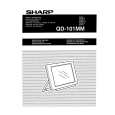
<Disassembling method> Please disassemble the QD-101MM according to the following procedure. (1)Remove four rear cabinet screws. (2)Disconnect the FPC cable from the LCD panel. (3)Disconnect the Inverter PWB connector from the Inverter PWB. (4)Disconnect the speaker connector and fan motor connector from the Main PWB. (5)Disconnect the Switch PWB connector from the Switch PWB. (6)Separate the rear cabinet from the front cabinet. (7)Remove four Main PWB screws. (8)Remove two D-sub connector screws. (9)Remove the Main PWB. (10)Remove the shield board(B). (11)Remove two connector angle screws. (12)Remove the connector angle. (13)Remove two Inverter PWB screws. (14)Disconnect the Backlight connector from the Inveter PWB. (15)Remove the Inverter PWB. (16)Remove four shield board(A) screws. (17)Remove the shield board(A). (18)Remove the LCD panel. (19)Remove the Backlight screws. (20)Pull out the Backlight. (21)Remove three Switch PWB screws. (22)Remove the Switch PWB. (23)Remove the Key block. (24)Remove four speaker screws. (25)Remove the speaker. (26)Remove two fan motor screws. (27)Remove the fan motor. (28)Remove the stand arm cover screws. (29)Remove the stand arm cover. (30)Remove four stand arm assembly screws. (31)Remove the stand arm assembly.
63
|
|
|
> |
|