|
There are currently no product reviews.
 ;
Good quality, all schematics of few of models. There is also short form of user manual and regulation manual.
;
Perfect copy of the service manual. you can enlarge every page, and it comes up
with all details.
;
It´s very very nice manual with all, what i need. Original in good quality. Very fast business. Very much thanks...
;
Purchased the manual that I was looking for at a great price and could download it easily.. Great service experience and for future purchases I plan to use the site.
Thank you very much
;
Exactly what was needed to assess the product - excellent value and great service
R-2275 R-2285
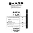
HOW TO RELEASE THE POSITIVE LOCK® CONNECTOR.
Terminal
Procedure 1. Pushing the lever of positive lock® conductor. 2. Pull down the connector from the terminal. 3. Now, the connector is free. Note: If the positive lock ® has a insulation sleeve, first remove it. If you do not so, you can not push the lever of positive lock ®. CAUTION: THE POSITIVE LOCK® TERMINAL CAN NOT BE DISCONNECTED BY ONLY PULLING. BECAUSE ONCE YOU (SERVICE PERSONAL) HAVE CONNECTED THE POSITIVE LOCK® CONNECTOR TO THE TERMINAL, THE POSITIVE LOCK® CONNECTOR HAS BEEN LOCKED.
Positive lock® connector 1 Push Lever
2 Pull down
Figure C-6. How to release the positive lock connector.
EXHAUST COVERS A AND B REMOVAL
(Exhaust cover A) 1. Remove the single (1) special screw holding the exhaust cover A to the rear cabinet, using the special driver LHSTIX DLR4-100T. 2. Release the tab of the exhaust cover A from the hole of the rear cabinet, and remove the exhaust cover A. 3. Now, the exhaust cover A is free. (Exhaust cover B) 1. Remove the single (1) special screw holding the exhaust cover B to the rear cabinet, using the special driver LHSTIX DLR4-100T). 2. Release the tab of the exhaust cover B from the hole of the rear cabinet, and remove the exhaust cover B. 3. Now, the exhaust cover A is free.
SCREW DRIVER TYPE: LHSTIX DLR4-100T
SPECIAL SCREW
NOTE: When securing or loosening the special screw, LHSTIX DLR4-100T TYPE screw driver should be used.
26
 $4.99 R2285 SHARP
Owner's Manual Complete owner's manual in digital format. The manual will be available for download as PDF file aft…
|