|
There are currently no product reviews.
 ;
have download a number of manuals todate , most are excellant, one or two sometimes a little difficult to read but a least avaialable, great site .
Brad.
;
Excellent had everything I wanted, very happy with purchase
 ;
This service is relatively cheap, document is fast available, schematic is readable.
Thanks.
;
So far I´m a satisfied customer. I have only downloaded "TECHNICS SX-KN470 Service Manual" maybe I will use it later.
Best regards
Peter
;
Good manual. It is complete and of high quality, both text and graphics. The schematics are with the original big size, so it can be viewed or printed without any loss of resulution and sharpness.
RC-BZ5LB/BZ5RD RC-BZ6BU
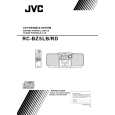
Removing the main board (See Fig.17 to 19)
Prior to performing the following procedure, remove the CD / cassette and amplifier assembly, the CD cover and door unit and the CD mechanism assembly. 1. Disconnect the harnesses from connector CN301 and CN308 on the main board (The harnesses are extending from the cassette mechanism assembly). 2. Disconnect the harness from connector CN702 on the key switch/display board (RC-BZ5 only).
Fig.17
CN308 CN702 Key switch/display bord
CN301
Main board
3. Remove the two screws G on the underside of the main board and release the two joint tabs f from the chassis in the direction of the arrow. ATTENTION: When reassembling, get the harness extending from FW301 and FW302 on the main board through the two slots g of the chassis. Get the card wire extending from CN304 on the main board through the hook h and the slot i.
Main board Joint tab f
Joint tab f
G
Fig.18
g
Chassis FW302(RC-BZ5 only)
g
h
i CN304
FW301
Fig.19
1-11
 $4.99 RCBZ5LB JVC
Owner's Manual Complete owner's manual in digital format. The manual will be available for download as PDF file aft…
|