|
There are currently no product reviews.
 ;
I was skeptical at first but later found the manual to be good quality for the price. It took a couple hours to receive the email with the download link, well worth the wait. Thanks.
;
very helpful, I could not have cleaned motherboard and replaced the main fan without it
 ;
Good manual, schematics nice and clear with good quality scanning. Woul dhave been nice to have immediate access after purchasing though.
;
I was very glad recieving the service manal from You. Manuals were delivered promptly and were correct as advertised. A complete and very usefull service manual with all details. Thank you!
;
Very clear copy. No pages missing. Big bonus is that it includes supplement. Price is affordable compared to what others ask for.
RC-BZ5LB/BZ5RD RC-BZ6BU
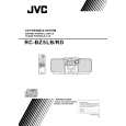
Removing the main board (See Fig.17 to 19)
Prior to performing the following procedure, remove the CD / cassette and amplifier assembly, the CD cover and door unit and the CD mechanism assembly. 1. Disconnect the harnesses from connector CN301 and CN308 on the main board (The harnesses are extending from the cassette mechanism assembly). 2. Disconnect the harness from connector CN702 on the key switch/display board (RC-BZ5 only).
Fig.17
CN308 CN702 Key switch/display bord
CN301
Main board
3. Remove the two screws G on the underside of the main board and release the two joint tabs f from the chassis in the direction of the arrow. ATTENTION: When reassembling, get the harness extending from FW301 and FW302 on the main board through the two slots g of the chassis. Get the card wire extending from CN304 on the main board through the hook h and the slot i.
Main board Joint tab f
Joint tab f
G
Fig.18
g
Chassis FW302(RC-BZ5 only)
g
h
i CN304
FW301
Fig.19
1-11
 $4.99 RCBZ5RD JVC
Owner's Manual Complete owner's manual in digital format. The manual will be available for download as PDF file aft…
|