|
|
|
Categories
|
|
Information
|
|
Featured Product
|
|
|
 |
|
|
There are currently no product reviews.
 ;
The service manual is a good quality scan of the Panasonic NV-850, which is electrically identical to the Philips VR 6920, but mecanically just nearly.
;
The service manual is a good quality scan of the Blaupunkt RTV-404, which is electrically and mecanically identical to the Panasonic NV-830.
;
completo manual bien detallado y de buena calidad de impresion , se echa en falta los esquemas de placa y parte de algun diagrama.
 ;
perfecto manual ,completo y detallado de muy buena calidad de impresion, ideal en una palabra.
;
un manual completo con una calidad de imagen buena con explicaciones en varios idiomas de los ajustes y detalles en conjunto un OK.
RC-V7
CIRCUIT DESCRIPTION
Panel Section (LCD ASSY: B38-0772-65)
The panel section controls serial communications with the main unit control section, the key input circuit, the display circuit, and the dimmer circuit through the microprocessor (IC4).
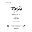
� Display circuit
Display section is a 152x45-dot full-dot matrix LCD controlled by two LCD. As shown in Figure 1, the master IC (IC5) side is connected to 32 common dots and 80 segment dots and the slave IC (IC6) side is connected to 13 common dots and 72 segment dots. The LCD drive voltage is obtained by raising the power supply voltage (5V) within the IC. Also, the contrast level (LEBEL8) for resetting is adjusted with R19 to be optimum.
� Serial communications circuit
A buffer is inserted in order to protect the microprocessor ports.
� Key input circuit
There is one microprocessor port for each panel section key. The PSW key is pulled down and the other keys are pulled up with software within the microprocessor. The rotary encoder is input directly to the microprocessor.
32 COM
LCD 152 X 45(dot) 80 SEG LCD Driver IC 5 72 SEG LCD Driver IC 6 13 COM
Microprocessor IC4
Fig. 1 Display circuit
9V LED1 R57 LED2 LED3 LED4
� Dimmer circuit
The dimmer circuit switches the lamp brightness to one of four levels or OFF. (See Table 1.) The current flowing to the LEDs is varied by selecting resistors from R55 to R58. Dimmer level 1 2 3 4 OFF P60 H L L L L P61 L H L L L P62 L L H L L P63 L L L H L
P62 IC4 Microprocessor
R58
P60 Q13 P61 Q12
Table 1 Port logic
Q11 P63 Q10
Fig. 2 Dimmer circuit 2
R56
R55
|
|
|
> |
|