|
|
|
Categories
|
|
Information
|
|
Featured Product
|
|
|
 |
|
|
There are currently no product reviews.
 ;
German user manual with schematics
GREAT INFORMATION AT VERY LOW PRICE!
A++
;
Excellent printing quality.
A complete and very usefull service manual with all details.
GREAT SERVICE AT VERY LOW PRICE!
A++
;
Excellent printing quality.
A complete and very usefull service manual with all details.
GREAT SERVICE AT VERY LOW PRICE!
A++
;
Excellent printing quality.
A complete and very usefull service manual with all details.
GREAT SERVICE AT VERY LOW PRICE!
A++
;
Excellent printing quality.
A complete and very usefull service manual with all details.
GREAT SERVICE AT VERY LOW PRICE!
A++
RDA-7 ADJUSTMENT PROCEDURES
Channel Test
1. Connect the assembled channel to the power transformer and turn it ON. 2. After about 9 seconds the two green LED's should turn ON 3. Measure the following voltages and make sure they are within the specifications: For all these measurements connect the DC voltmeter negative lead to the bottom lead of the VR8 zener diode. C7 (+) C9 (-) L1 70V +/- 3V -70V +/- 3V 0V +/- .1V 4. Connect a DC voltmeter to the test points TP1 and TP2 and adjust the voltage to 4mV using the R46 BIAS adjustment trimpot. 5. Allow the channel to warm up for 30 minutes, adjusting the bias every ten minutes. 6. Measure the output DC voltage and adjust it as close to zero as possible using the R24 trimpot.
Main Chassis Test
1. Assemble the chassis/power supply and configure it for right line voltage. 2. Plug it into the power line. 3. Turn the unit ON. The blue ON LED should come ON. 4. Red Fault/Standby LED should be flashing. 5. Turn the unit OFF and plug a remote control plug into the Remote IN jack. 6. Turn the unit ON. The Red Standby LED should be ON. 7. Apply 12V to the remote control plug. The unit should turn ON, the blue LED should be ON and the red LED flashing. 8. Measure the secondary voltages on all power cables going to the channels. Each secondary should read 50VAC +/- 2VAC.
Final Assembly Test
1. Install all channels in the chassis and turn the unit ON. All green LED's should come ON after about 9 seconds. 2. Check bias currents on all channels and adjust if necessary. 3. Allow the unit to warm up for 30 minutes, adjusting the bias currents every ten minutes. 4. Adjust the DC output voltage as close to zero as possible on each channel.
18
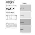 $4.99 RDA7 INTEGRA
Owner's Manual Complete owner's manual in digital format. The manual will be available for download as PDF file aft…
|
|
|
> |
|