|
There are currently no product reviews.
 ;
Thank you very much you are helping me a lot with my preferred hobby!!! this manual of an old TV is going to be very helpful!!!!
You are very honest competent great job very clear and well done!!!!
Matteo
;
An excellent service manual contains dismantling locations of components, electronic adjustments,worth the money.
;
Caracteristiques,circuit adjusment,notes on schematis diagram,it's a good service manual,to live well,thanks.
;
Service Manual in good quality, with all of the pages.
;
Very usrfull for repaur, great quality copy. includes complete parts list and schematics
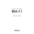
RDA-7.1 ADJUSTMENT PROCEDURE-1
BIAS & DC Offset Adjustment
1. Connect the assembled channel to the power transformer. 2. Connect the power cord into an AC wall outlet. 3. Turn ON the unit. After about 3 seconds the two green LED's should turn ON. Measure the following voltages and make sure they are within the specifications. C7 (+) : 70 V +/- 3 V C9 (-) : -70 V +/- 3 V L1 : 0 V +/- 0.1 V 4. Connect the DC voltmeter to the test points TP1 (-) and TP2 (+) and adjust the voltage to 4 mV using the R46 BIAS adjustment trimming resistor. 5. Allow the channel to warm up for 30 minutes, adjusting the bias currents every 10 minutes. 6. Measure the output DC voltage and adjust it as close to zero as possible using the R24 trimming resistor.
Main Chassis Check
1. 2. 3. 4. 5. 6. 7. Assemble the chassis / power supply. Connect the power cord into an AC wall outlet. Turn ON the unit. The blue ON LED should come ON. Turn OFF the unit and plug a remote control plug into the Remote IN jack. Turn ON the unit. The Red Standby LED should be ON. Apply 12V to the remote control plug. The unit should turn ON, the blue LED should be ON. Measure the secondary voltages on all power cables going to the channels. Each secondary should read 50 VAC +/- 2 VAC.
|