|
|
|
Categories
|
|
Information
|
|
Featured Product
|
|
|
 |
|
|
There are currently no product reviews.
 ;
Good price for the manual and easy to locate on the site and download. Plus, just like the original. Thanks a lot.
;
Genuine Service Manual. Link was available in less then an hour or so. Service Manual contains assembly, PCB layout, complete circuit diagram, Components list etc
;
Great and very well scanned Service Manual, also very fast download - Recomended !
;
I'm quite impressed. I had to wait 24 hours for my manual (quite a rare one) but I got it and the quality was good. Also, from trawling the web, these prices are by far the best.
;
Manuale perfetto. Ottimo e utilissimo. Grazie a questo manuale ho potuto realmente risolvere il complesso problema della stampante.
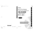
5. To shift the CTL waveform, press CH UP or CH DOWN button on the remote control unit. Then make sure that the maximum output position of PB FM envelope signal becomes within ±2ms from preset position.
either at the beginning or end of track as shown in Fig. M10.
Dropping envelope level at the beginning of track.
Good
FM envelope signal 2ms Center Position
Fig. M8
Dropping envelope level at the end of track.
FM envelope output signal is adjusted at maximum. CTL signal
No Good
FM envelope output signal is low.
Fig. M7
6. Set the Tracking Control Circuit to the preset position by pressing CH UP button and then �PLAY� button on the unit.
Fig. M9 Envelope is adjusted properly. (No envelope drop)
1-C. Checking/Adjustment of Envelope Waveform
Purpose: To achieve a satisfactory picture, adjust the Guide Rollers so that the PB FM envelope becomes as flat as possible. Symptom of Misalignment: If the envelope output is poor, noise will appear in the picture. The tracking will then lose precision and the playback picture will be distorted by any slight variation of the Tracking Control Circuit. 1. Connect the oscilloscope to TP301 (C-PB) on the Main CBA. Use TP504 (RF-SW) as a trigger. 2. Playback the Gray Scale on the Alignment Tape (FL6NS8). Set the Tracking Control Circuit to the preset position by pressing CH UP button and then �PLAY� button on the unit. Adjust the height of Guide Rollers [2] and [3] (Fig. M3, Page 2-3-3) watching the oscilloscope display so that the envelope becomes as flat as possible. To do this adjustment, turn the top of the Guide Roller with the Guide Roller Adj. Screwdriver. 3. If the envelope is as shown in Fig. M8, adjust the height of Guide Roller [2] (Refer to Fig. M3) so that the waveform looks like the one shown in Fig. M10. 4. If the envelope is as shown in Fig. M9, adjust the height of Guide Roller [3] (Refer to Fig. M3) so that the waveform looks like the one shown in Fig. M10. 5. When Guide Rollers [2] and [3] (Refer to Fig. M3) are aligned properly, there is no envelope drop 2-3-4 D5P4HSMA
Fig. M10
Note: Upon completion of the adjustment of Guide Rollers [2] and [3] (Refer to Fig. M3), check the X Value by pushing the CH UP or DOWN buttons on the unit alternately, to check the symmetry of the envelope. Check the number of pushes to ensure preset position. The number of pushes of the CH UP button on the unit to achieve 1/2 level of envelope should match the number of pushes of the CH DOWN button on the unit from center. If required, redo the �X Value Alignment.�
|
|
|
> |
|