|
|
|
Categories
|
|
Information
|
|
Featured Product
|
|
|
 |
|
|
There are currently no product reviews.
 ;
Speedy transaction with a quick download. Awesome hassle-free service.
;
very poolite and healpful secure transaction thanks allot
;
- Very good scan quality, PERFECT!
- Sehr gute scan Qualitaet, empfehlenswert!
Wolfgang Sundhaus
 ;
Good site, works ok and you get what you order, no problems experienced, got my manual within a day. A++++
;
Original well scanned manual. Got the job done. Microwave problem found & corrected. For $5 and a new magnitron from ebay, it was a cheap and good the first shot fix. Electrical schematics allowed me to mage sure every thing else was ok before cutting and order for parts. Hard to live without.
1
2
3
4
RFD-1
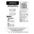
4. PCB CONNECTION DIAGRAM
4.1 DEM ASSY
A
KUC type : HOUSING ASSY(VKP2182) SD type : VOLTAGE SELECTOR
A DEM ASSY
B CN11
B
C CN3
POWER TRANSFORMER
NOTE FOR PCB DIAGRAMS:
1. Part numbers in PCB diagrams match those in the schematic diagrams. 2. A comparison between the main parts of PCB and schematic diagrams is shown below.
Symbol in PCB Diagrams Symbol in Schematic Diagrams Part Name
B BCE
C
EB
C
E Transistor
C
BCE
B
C
EB
C
E Transistor with resistor
D DGS
G
SD
G
S Field effect transistor
Resistor array
3-terminal regulator 3. The parts mounted on this PCB include all necessary parts for several destination. For further information for respective destinations, be sure to check with the schematic diagram. 4. Viewpoint of PCB diagrams
(VNP1649-A) Q5 Q4 Q1 Q2 IC201 IC200 IC5 IC3 IC9 IC7 Q3 Q6 IC1 IC2 IC6 IC8 IC4
Connector
Capacitor Chip Part
D
SIDE A
P.C.Board
SIDE B
SIDE A
8
A
1 2 3 4
|
|
|
> |
|