|
|
|
Categories
|
|
Information
|
|
Featured Product
|
|
|
 |
|
|
There are currently no product reviews.
 ;
Received a quick response, material was exactly what it was supposed to be. The service did everything I expected it to do. would use service again.
;
Detailed SONY CFD980 Service Manual at an easy to find one stop shopping. Make my radio hobby technically interesting. Thanks.
 ;
Excellent service from Owner-Manuals.com, good prices and quick turn around. The supplied PDF was good enough quality to be enlarged sufficiently to read component values.
;
Very complete shop manual. It contains everything needed to troubleshoot bascially any problem. Instructions, diagrams, schmeatics, illustrations... it's all there. Highly recommended!
;
Great product, very good quality, found all needed information. Thanks
RHT-G2000 SECTION 4 DIAGRAMS
� Note for Printed Wiring Boards and Schematic Diagrams
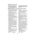
Note on Schematic Diagrams. � All capacitors are in µF unless otherwise noted. (p: pF) 50 WV or less are not indicated except for electrolytics and tantalums. � All resistors are in � and 1/4 W or less unless otherwise specified. � % : indicates tolerance. � f : internal tolerance. � 2 : nonflammable resistor. � C : panel designation. Note: The components identified by mark 0 or dotted line with mark 0 are critical for safety. Replace only with part number specified. Note: Les composants identifiés par une marque 0 sont critiques pour la sécurité. Ne les remplacer que par une piéce portant le numéro spécifié. Note on Printed Wiring Boards. � X : parts extracted from the component side � Y : parts extracted from the conductor side � a : Through hole � : Pattern from the side which enables seeing (The other layers' patterns are not indicated.) Caution: Pattern face side: (Side B) Parts face side: (Side A)
Parts on the pattern face side seen from the pattern face are indicated. Parts on the parts face side seen from the parts face are indicated.
� A : B+ Line. � Voltages and waveforms are dc with respect to ground under nosignal conditions. no mark : DVD ( ) : FM � Voltages are taken with a VOM (Input impedance 10 M�). Voltage variations may be noted due to normal production tolerances. � Waveforms are taken with a oscilloscope. Voltage variations may be noted due to normal production tolerances. � Circled numbers refer to waveforms. � Signal path. F : AUDIO d : TUNER f : DIGITAL IN E :Y r : COMPONENT VIDEO L : VIDEO
� Waverforms
1 IC509 qd (XOUT)
3.1 Vp-p
3 IC506 qs (MCLK2)
4.2 Vp-p
202 ns 1 V/DIV, 100 ns/DIV 71.9 ns 1 V/DIV, 20 ns/DIV
2 IC505 wa (XOUT)
4.2 Vp-p
4 IC108 rk (XFSOIN)
1.8 Vp-p
81.3 ns 1 V/DIV, 20 ns/DIV
20.2 ns 0.5 V/DIV, 20 ns/DIV
8
|
|
|
> |
|