|
|
|
Categories
|
|
Information
|
|
Featured Product
|
|
|
 |
|
|
There are currently no product reviews.
 ;
I purchased the unit from a private party and the original owners manual was not available. Having the ability to download it was extremely helpful and clarified operating the equipment immensely. This is a complicated unit and without the manual I would not have been able to maximize it's potential. Thank you.
;
Being a user of older radios of many kinds, preferring them over more modern rigs, this manual was invaluable in the programming of my two. I now know for certain what the assorted buttons functions are, and am very grateful to have found this excellent site. Many thanks for your assistance, Tony.
 ;
Clear and easy to read. All details as expected. Price acceptable , and quick delivery.
;
Quick response and exactly what I was looking for and at a great fair price!
;
5 star quality on these downloadable manuals. Easy to read and all the information is there. A must when doing a custom install or needing to service your precious old school electronics.
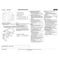
Maintenance
Checking and adjusting the steering wires
The steering is controlled by means of wires. These can in time become slack, which implies that the adjustment of the steering becomes altered. Check and adjust the steering as follows: 1 Remove the frame plate by loosening the screws (2) and lift the frame plate by the rear edge.
Checking the brake Rider 11 and Rider 11 C
The brake is a disc brake and is located on the gearbox. Check that the brake is adjusted correctly by measuring the distance between the brake lever and front edge of the cut-out on the chassis. The distance should be 0-1 mm (0-0.040') when the brake is not actuated.
2
Check the tension of the steering wires by squeezing them together by the arrows as illustrated. It should be possible to push them together so that the distance between them is half as much, without using unnecessary force.
Adjusting the brake Rider 11 and Rider 11 C
2
1
1
1 2
Loosen the locking nuts (1). Tension the cable with the adjuster screw (2) so that the distance between the brake lever and front edge of the cut-out on the chassis is 1 mm (0.040�). Tighten the locking nuts (1) after adjustment.
3 3 If necessary, the wires can be adjusted by tightening the adjuster nuts on each side of the steering collar. Do not over tighten the cables; they should only be drawn in towards the steering collar.
Checking and adjusting the brake on Rider 13 C and Rider 15 C
Check that the brake is correctly adjusted by placing the machine on a slight downhill slope with the clutch disengaged and activating the brake. When the machine does not stand still, the brake should be adjusted according to the following.
Hold the cable, for example using an adjustable wrench, so that it does not twist. If you only tension one side the steering wheel�s centre position may change. Check the wire tension on completion of the adjustment as per item 2. 1 2 3 4 Loosen the locking nuts (1). Tension the cable using the adjuster screw (2) until the play in the cable is taken up. Tighten the locking nuts (1). The brake should be checked again after adjustment
22 � English
|
|
|
> |
|