|
|
|
Categories
|
|
Information
|
|
Featured Product
|
|
|
 |
|
|
There are currently no product reviews.
 ;
The Service Manual for the Kenwood KR-V55R provided by owner-manuals.com was as described/advertised. The contents provided the necessary information to effect a diagnosis of the unit. The schematics above all else was instrumental in tracing the the signal flow from component to component.
 ;
This manual was the factory original. Excellent value and contained all the details I needed. Easy dowwnload provided the information when I needed it.
;
Impeccable, document très complet. Perfect, i get all i need. All schematic are correct. Thanks
;
The manual is of better quality compared to other. I found it less expensive and therefore it it is the best buy cost vs quality.
;
I bought the service-manual of the sony ICB-1020(an old transmitter-receiver) at "www.Owners-Manual.com", I found the service-manual for a fairly cheap price(in comparison with other sellers). I filled in some questions, payed the order with Ideal, and within 24 hours I had my service manual. I was very happy:In no time I had my service-manual and everything, but literally everything was noted down in the manual; the electronic scheme, the parts list, etcetera.
A very practical, reference-document.
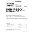
RMD-V3104U Rear Panel
1 2 345
INPUT OPTION
V IN
6
7 89 0 - =
COMB OUT
CONTROL IN
DISPLAY
MVP RS-232C RATE MODE
INPUT
V.FIL ON OFF G ( VBS) ( VBS) (Y/C) (Y)
OPTION B (C) R H/CS V
V IN VBS Y/C VBS Y
C
OUTPUT
AC INLET FUSE 125V 3.15A
V OUT1 VBS G Y B C R VBS G
V OUT2 Y B C R
V OUT3 VBS G Y B C R VBS G
V OUT4 Y B C R
~
1 VBS/ Y/C switch
!
@
#
$
Connects RS-232C cable.
%
6 RS-232C connector
Selects whether the VBS (video signal) or Y/C signals are input to the V IN (Video) input. The factory preset is VBS (video signal).
< RS-232C connector diagram > RS-232C pin layout
13 1
2 V.FIL (Vertical interpolation filter) ON/OFF switch
When the optional variable scan board (RMD-V3020) is installed, use this switch to switch the vertical interpolation filter ON/OFF. Set this switch to ON if the top and bottom of the computer screen image cannot be accommodated entirely by the screen. The factory preset is set to ON.
25
14
3 INPUT switch
Selects whether the V IN (Video) or OPTION input is enlarged into 4 screens. The factory preset is set to V IN. � Always press the reset button after changing the position of this switch.
< RS-232C connection diagram > Use an RS-232C straight cable for connection.
< External computer >
FG TxD RxD RTS CTS DSR SG 1 2 3 4 5 6 7 RS-232C straight cable 1 2 3 4 5 6 7
< MVP unit >
RS-232C IN connector
FG RxD TxD RTSI CTSI DSRI SG
4 Remote control input connector
Connects the display's remote control unit. (Adjustment or changes to the settings of the unit cannot be accomplished with the remote control unit.)
� Pins 4, 5 and 6 are internally shorted.
5 RS-232C switch
When performing adjustments from a computer, use this switch to switch between this unit (MVP) and display (DISPLAY). Pins which are not shown in the diagram are not used.
92
|
|
|
> |
|