|
|
|
Categories
|
|
Information
|
|
Featured Product
|
|
|
 |
|
|
There are currently no product reviews.
 ;
Wanting to repair a neighbours tape recorder I needed the necessary information, it makes it easier. Although the service manual is described as "Language : English" To my dismay I found that it is entirely written in German, a language I do not understand. At least I now have the schematics which will help of sorts. I may not use this service again due to the laguage difficulty after all when it states English you do not expect it to be entirely in another language.
 ;
GOOD SERVICE MANUAL.I ALWAYS BUY THERE IF I FIND WHAT I AM LOKING
;
Good quality (clearly readable) manual, I'm glad I could find it here, at a bargain price!
;
Speedy transaction with a quick download. Awesome hassle-free service.
;
very poolite and healpful secure transaction thanks allot
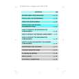
No.
Item
Measuring instruments & Input signals � IN MEGA chart (precisely scanned size) � Oscilloscope (H-rate)
Mode
Measuring point ( * ) Adjustment parts ( - ) Adjustment level ( + )
Adjustment procedure
2
Frequency response adjustment
� BARS swtch: � R Channel OFF * See Measuring Point � Menu No. 2A Table. LENGTH: - VR202 (R FREQ) 20 M [Main board] + Same levels of the 6 MHz section � G Channel * See Measuring Point Table. - VR302 (G LEVEL) [Main board] + Same levels of the 6 MHz section
6 MHz
1. Shoot the IN MEGA chart so that it becomes precisely scanned size. 2. Connect oscilloscope CH1 and CH2 as shown in the Measuring Point Table. 3. Adjust so that the levels of CH1 and CH2 of the 6 MHz sections are same levels.
4. Adjust in the same way as the R Channel.
CH1 Same level CH2
� B Channel * See Measuring Point Table. - VR402 (B LEVEL) [Main board] + Same levels of the 6 MHz section
2.6
INTERCOM LEVEL ADJUSTMENT
For intercom operation using headsets, the intercom levels can be adjusted with the following controls. � Camera : INCOM LEVEL control on the adapter at the rear. � RM-P210 : INTERCOM LEVEL control on the front panel. Although adjustments on the circuit board are usually unnecessary, perform the following adjustment if the amplification gain seems to be insufficient. 1 Side tone adjustment (Feedback of the microphone to the earphone of the same headset) Headset � S602: 2W [Main board] * INTERCOM jack on the 1. Connect 560 � resistance across H and C INRM-P210 front panel TERCOM terminals on the rear panel. - VR15 (2W S.TONE) 2. Plug the headset into the front panel INTER[Main board] COM jack. 3. Talk and adjust to optimize the side tone level. (Adjust it to the clockwise direction.)
2
RTS side tone RTS headset adjustment (U model only)
� S602: RTS [Main board]
* INTERCOM jack on the 1. Connect 220 � resistance across H and G INRM-P210 front panel TERCOM terminals on the rear panel. - VR16 (RTS S.TONE) 2. Plug the headset into the front panel INTER[Main board] COM jack. 3. Talk and adjust to optimize the side tone level. (Adjust it to the clockwise direction.)
2-5
 $4.99 RM-P210E JVC
Owner's Manual Complete owner's manual in digital format. The manual will be available for download as PDF file aft…
|
|
|
> |
|