|
|
|
Categories
|
|
Information
|
|
Featured Product
|
|
|
 |
|
|
There are currently no product reviews.
 ;
hat alles sehr gut geklappt. Das Servicemaual ist gut zu verwenden. Die Pläne und Schrift
ist klar und leserlich. Außerdem preiswert. Grüße an alle Hifi-Bastler
;
I got the manual quickly after the payment was transfered (1 day). The manual was exactly what i needed and the updates via e-mail were great. Thanx!
;
I've looked for this manual all over that internet, you guys had it and to a good price. A++++
;
I've looked some time for this manual, you guys had it and to a good price. A++++
 ;
factory technician level - complete with board views :
( removing chassis from cabinet , only thing missing ) ;
on weekends , staff is not available so - be patient .
3-7-2. Video Memory SIZE/SHIFT/BLKG Adjustments
1. Input the monoscope signal to VIDEO IN. 2. Press the INPUT SELECT VIDEO key to project the monoscope signal on the screen. 3. Select VIDEO MEMORY 1 using the SWITCHER/ VIDEO MEMORY/INDEX changing switch and the SWITCHER/VIDEO MEMORY/INDEX key. 4. Press the RGB SHIFT key and adjust the center of the monoscope signal to the screen center using the �, �, � and � keys. 5. Press the RGB SIZE key and adjust the horizontal and vertical sizes of the monoscope signal to 4:3 using the �, �, � and � keys. 6. Press the BLKG key to adjust the screen top blanking to the position 40 ± 10 mm outside the effective screen using � and � keys. 7. Press the MEMORY key. 8. Store the data of VIDEO MEMORY 1 to VIDEO MEMORY 2 to 5, too. 9. Select VIDEO MEMORY 6. 10. Press the RGB SHIFT key and adjust the center of the monoscope signal to the screen center using the �, �, � and � keys. 11. Press the RGB SIZE key and adjust the horizontal and vertical sizes of the monoscope signal to 4:3 using the �, �, � and � keys. 12. Press the BLKG key to adjust the screen top blanking to the position 40 ± 10 mm outside the effective screen using � and � keys. 13. Store the data of VIDEO MEMORY 6 to VIDEO MEMORY 7_10, too.
3-8. HIGH VOLTAGE SCREEN DISTORTION ADJUSTMENT
1. Select INPUT A and input the fH = 64 kHz RGB stripe signal to the RGB terminals. 2. Press CONTR (+) and BRIGHT (+) to set the contrast and bright levels to the maximum. 3. Adjust RV1 of the EA board so that the left and right vertical lines of the stripes can be straight.
NG
OK
3-9. PROCEDURE AFTER COMPLETING ADJUSTMENTS
After completing all adjustment, change the dip switch S201-1 on the YA board from �OFF (right)� to �ON (left)� to save the adjustment data in the memory.
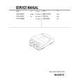
VPH-G90E/G90U/G90M
3-19
|
|
|
> |
|