|
|
|
Categories
|
|
Information
|
|
Featured Product
|
|
|
 |
|
|
There are currently no product reviews.
 ;
Happy to find finally a schematic for this amplifier. The schematic is of good quality, the pcb layout is useless: all is black. Never the less, it is very easy to find the components on the board using the schematics.
;
Hard to find manual was ready the next day. Scans were very legible (including schematics). All the essential parts of the service manual were present (adjustment procedure, schematics, and parts list). It would have been nice if the rest of the manual was included (disassembly procedure, theory of operation, etc.).
 ;
The Service Manual for the Kenwood KR-V55R provided by owner-manuals.com was as described/advertised. The contents provided the necessary information to effect a diagnosis of the unit. The schematics above all else was instrumental in tracing the the signal flow from component to component.
;
This manual was the factory original. Excellent value and contained all the details I needed. Easy dowwnload provided the information when I needed it.
;
Impeccable, document très complet. Perfect, i get all i need. All schematic are correct. Thanks
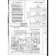
SLV-E850B/E850UX/E880EG/F900B/F900NP/F900UX/F900VC/F990B/F990NP/F990UX/F990VC
RP-231 (REC/PB AMP) SCHEMATIC DIAGRAM � Ref. No.: RP-231 Board; 1,000 Series �
THIS NOTE IS COMMON FOR PRINTED WIRING BOARDS AND SCHEMATIC DIAGRAMS. (In addition to this, the necessary note is printed in each block.)
� For printed wiring boards. � : Pattern from the side which enables seeing. � + : Through hole. Caution : Pattern face side: (Conductor Side)
Parts on the pattern face side seen from the pattern face are indicated. Pattern face side: parts on the parts face side seen (Component Side) from the parts face are indicated.
� For schematic diagrams. � Caution when replacing chip parts. New parts must be attached after removal of chip. Be careful not to heat the minus side of tantalum capacitor, because it is damaged by the heat. � All resistor are in ohms, 1/4W unless otherwise noted. Chip resistor are 1/10W unless otherwise noted. k�: 1000�, M�, : 1000k�. � All capacitors are in µF unless otherwise noted. pF : µ µF. 50V or less are not indicated except for electrolytics and tantalums. � : panel designation. � : internal component. � : B+ Line. � : B� Line. � : IN/OUT direction of (+,�) B LINE. � Circled numbers refer to waveforms. � Readings are taken with a PAL color-bar signal input. � Voltage are dc between ground and measurement points. � Readings are taken with a digital multimeter (DC10M�). � Voltage variations may be noted due to normal production tolerances.
When indicating parts by reference number, please include the board name.
4-5
4-6
4-7
REC/PB AMP
RP-231
|
|
|
> |
|