|
|
|
Categories
|
|
Information
|
|
Featured Product
|
|
|
 |
|
|
There are currently no product reviews.
 ;
Excellent transaction - clean document received - Thanks a lot
;
Manual is in German but complete. I needed this one to fix a long lasting problem with the internal PSU of the camera. Most of the capacitors begin to leak after a few years wich results in the inability to power on the camera. When you try to turn it on the power led flickers and the unit directly turns off. Thanks to this manual I was able to locate all bad cap's and to dis- and reassemble the camera without any problems.
 ;
We received the manual in a timely manner and it was exactly what we were expecting.
;
Excellant, finally this is want I need and searching for The service manual is fantastic and thank you to owner-manuals.com and its service. Price is reasonable. It's a bit slow on my end in downloading but manage to receive the whole manual without a break. once again, thanks.
;
Very good scanning quality. All schematics are very legible. Worth every cent !
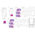
2-7. DISCONNECTING/CONNECTING THE FLEXIBLE CARD WIRE
The three flexible card wires are used as follows: Take care not to break the flexible card wire. This shorten the wire life. . Between DR-395 and DU-35 . Between LCD monitor and DR-395 . Between Backlight and DR-395 : Q�ty 1 : Q�ty 1 : Q�ty 1
Disconnecting
1. Turn off the power of the unit. Type A (between the DR-395 board and the DU-35 board, and the LCD monitor and the DR-395 board) 2. Lift up the portion A in the direction of the arrow and disconnect the flexible card wire. Type B (between the backlight and the DR-395 board) 2. Slide portion B in the direction of the arrow and disconnect the flexible card wire.
Connecting
n . Be careful not to insert the flexible card wires obliquely. . Check that the conductive surface of the flexible card wire is not soiled with dust. Type A 1. Lift up the portion A in the direction of the arrow. Insert the flexible card wire as far as it will go into connector with the conductive surface of the wire put down. 2. Push down the portion A to secure the flexible card wire. Type B 1. Slide portion B in the direction of the arrow and insert the flexible card wire as far as it will go into connector with the conductive surface of the wire put down. 2. Slide portion B in the opposite direction of the arrow and lock each connector.
A
B
Conductive surface Type A
B Conductive surface Type B
RM-VJ1/VJ1P
2-7 (E)
|
|
|
> |
|