|
|
|
Categories
|
|
Information
|
|
Featured Product
|
|
|
 |
|
|
There are currently no product reviews.
 ;
y'm hapy for this shoping . Estoy feliz por esta compra , ahora puedo reparar mi equipo de audio que AMO . And very good price for this manual . Thank yuo .
;
Perfect manual, perfect service. Easy reading. Thanks a lot
;
Very good quality download here. Great hard to find manuals at a reasonable price.
 ;
I had a problem with the mains transformer, I did not know the voltages on the secondary, this manual helped me to solve this problem, thanks for the manual!
;
Great manual, great quality copy, complete parts reference and scematics, Thank you
Replacement of ICs
1. Using the braided wire, �SOLDER TAUL� (Sony Part No. 7-641-300-81), remove the solder around the pins of the IC-chip to be removed. 2. While heating up the pins, remove the pins one by one using sharp-pointed tweezers. 3. Make sure that there is no pattern peeling, damage and/ or bridge around the desoldering position. 4. After removing the chip part, presolder the area, in which the new chip part is to be placed, with a thin layer of solder. 5. Place new chip part in the desired position and solder the pins.
2. Insert the tool tongs into the slots of the carrier socket. Push fully in so that the tool butts on the socket at �A�.
"A"
"A" Chip Carrer (To be removed)
Chip Carrier Socket
4-7-3. Removal of PLCC IC (IC701/DPR-86A Board)
PLCC socket Extraction Tool (Sony Part No. J-6035-070-A) This extraction tool is useful for extracting the IC(PLCC type) inserted into an IC socket, and fits all sizes of ICs from 20 pins through 124 pins.
3. Place the thumb and the first and second finger on the ribbed area of the tool. Maintain a small downwartd force to keep the tool butted on the socket. Squeeze the thumb and finger together so that the tool legs tend to straighten. This action will draw the chip carrier out of the socket and grip it within the tool legs. Maintain the squeezing action so as to hold the chip in the tool, hold the tool over your other hand and relax the squeeze. The chip will fall out of the tool and into your hand.
Finger Thumb Chip Carrier
Chip Carrier Socket
NOTE: Do not try to pull chip carrier out of socket and let the tool action pull it out. Do not squeeze harder than necessary, only enough that the tool action occurs.
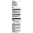
<How to use the Extraction Tool>
1. Spread or compress the tool legs so the tongs will fit into the slots of the chip carrier socket.
Hinge Pin Push this Portion
Push this Portion leg
Extraction claw
RSE-500/400 (UC) PMS-500P/400P (CE)
4-19
|
|
|
> |
|