|
|
|
Categories
|
|
Information
|
|
Featured Product
|
|
|
 |
|
|
There are currently no product reviews.
 ;
Exactly what was needed to assess the product - excellent value and great service
;
A site where discontinualed schematic diagrams and back dated information can be found on discontinued radios tv's and any electronic equipment can be found. Newer manuals either Service and operating manuals. Radio amateurs should find this site a great source for ham radio equipment manuals. I will return to this site should I need information on any electrical equipment. priced easy to download in a PDF format and print pages need to undertake the repair.
;
Quality scan of the original. All the detail necessary to troubleshoot, repair and adjust the unit. I'm sure I will be downloading more manuals in the future as the need arises.
;
Exactly as described, a Service Manual complete with the schematics and PCB layout delivered in a timely manner. Many thanks for the great service.
 ;
some of the writing is a bit blur but the part in the schmatic was great and i have fixed the machine thanks
RS-WP1WT
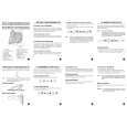
Removing the LCD board (See Fig.7 and 8)
LCD board
E
Prior to performing the following procedures, remove the rear panel assembly and the function switch board. 1. Remove the four screws E attaching the bracket. 2. Disconnect the card wire from connector CN421, CN422 and the wire from CN913 on the LCD board respectively. 3. Disconnect the wire from connector CN624 on the CD mechanism assembly. 4. Remove the two screws F attaching the LCD board (The LCD spare board and the LED board are still attached to the LCD board).
LCD board CN913
Bracket
E
Fig.7
F
CN421
Removing the headphone jack board (See Fig.9 and 10)
Prior to performing the following procedures, remove the rear panel assembly. 1. Remove the two screws G attaching the headphone jack board bracket. 2. Pull out the headphone jack board bracket and the headphone cover at the same time. 3. Remove the two screws H attaching the headphone jack board. 4. Disconnect the wire from connector CN711 on the headphone jack board.
F
CN422 CN624
Fig.8
G H
Headphone cover
G
Headphone jack board CN711 Headphone jack bracket
Fig.10
Fig.9
1-7
|
|
|
> |
|